- 8 -
Ref No 661C / Art No 980661
www.rotork.com www.remotecontrol.se
ROTORK SWEDEN AB
Box 80, Kontrollvägen 15, SE-791 22 Falun, Sweden
Tel: +46 (0)23-587 00 • Fax: +46 (0)23-587 45 • [email protected]
We reserve the right to
make changes without notice
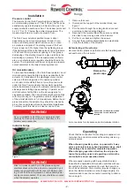
Pos 3
Pos 2
Pos 1
A
D
C
B
1. Make sure that the valve is fully closed.
2. To adjust the limit switches, the position transmitter need to
be dismounted. If limit switches are not used, please continue
at point 13.
3. Dismount the position transmitter by unscrewing the two
screws holding the connection terminal in the box. Move the
connection terminal sideways with the cables still attached. Pull
the position transmitter carefully straight out until it is released.
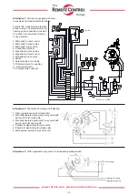
4. Attach suitable indication equipment to the limit switches in the
box indicating the closed and open position (view wiring dia-
gram sent with the box).
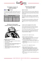
5. In cases where visual indication is used, turn the input shaft
of the gearbox (Figure B) to the position where the red indicator
points at closed position, i.e. 0%.
6. Adjust the cam of the limit switch indicating closed position by
loosening the socket head cap screw (Figure D pos. 3) and
turning the cam anti-clockwise to the position where the limit
switch starts to indicate. Fasten the cam in this position.
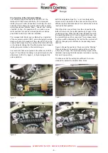
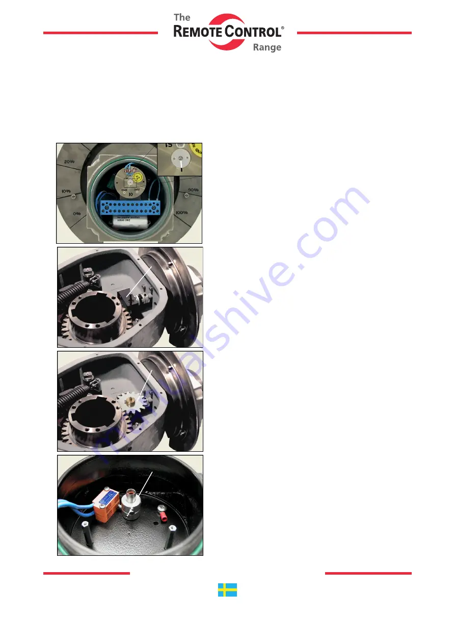
7. Mount the gear on the input shaft of the gearbox in the way that
it is free to rotate without touching the hub of the actuator. Mark
the position of the gear with a marker.
8. Rotate the gear clockwise the number of turns the valve need
to open, times two. 10.25 turns of the valve gives 20.5 turns of
the gear etc.
9. Adjust the cam of the limit switch indicating open position by
loosening the socket head cap screw (Figure D pos. 3) and
turning the cam clockwise to the position where the limit switch
start to indicate. Fasten the cam in this position.
10. In cases where visual indication is used, the hand should now
be pointing at open position, i.e. 100%.
11. Rotate the gear anti-clockwise back to the exact closed posi-
tion and check the number of turns of the valve.
12. Make sure that the marks on the backside of the position
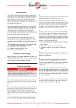
transmitter are lined up (Figure A). Put the position trans-
mitter back into the box by pushing its shaft into the O-ring
provided hole in the shaft of the box. Remount the terminal
block and check that the position of the position transmitter has
not changed.
13. The position transmitter shall be adjusted with its marks lined
up (Figure A) and possible limit switches and visual indication
shall show closed position.
14. Attach suitable indication equipment to the position trans-
mitter and possible limit switches (view wiring diagram sent
with the box).
15. Adjust the output signal from the position transmitter for
closed position (i.e. 4.00 mA) by turning the screw underneath
the protection plug marked with ”ZERO” on the position trans-
mitter (Figure A). Use a small flat screwdriver.
16. See point 7.
17. Rotate the gear clockwise to the position where the limit
switch indicate open position. In cases where limit switches are
not used, see point 8.
18. Adjust the output signal from the position transmitter for open
position (i.e. 20.00 mA) by turning the screw underneath the
protection plug marked with ”SPAN” on the position transmitter
(Figure A).
19. Repeat point 15 and 18 a couple of times until a stable output
signal is received from the position transmitter.
20. Rotate the gear to closed position and mount it according to
Figure C.
21. Try to manually operate the actuator and check the signals.
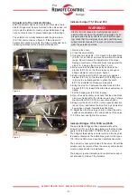
Complete adjustment of box 1990
The limit switches are the primary indication of the
box. In cases where limit switches are not used, the
position transmitter of the box is the primary indica-
tion. In cases where visual indication is used, caution
shall be taken to avoid the indicator to exceed the
endpoints of the scale in any occasion. If this happens
the indicator and the through shaft can be damaged.


