7
Established Leaders in Actuation Technology
4
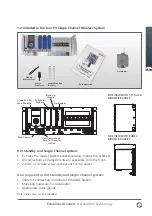
Emergency Shut Down
If Emergency Shut Down is required, place
the ESD button between pins 4 & 5.
If Emergency Shut Down is not required,
link pins 4 and 5 together.
5
For RS232 Serial Data
Connect a cable to CPU A port 2
(and another to CPU B port 2 on hot
standby systems).
5 For RS485 Serial Data
Connect a cable to CPU A port 1.
(The system automatically links the
connection to port 1 on CPU B).
Note: See page 13 for port defaults.
1
2
3
4
5
6
7
8
9
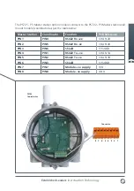
9 way Female D Type
RS232 Connections
Signal Common
Data into P3
Data out
from P3
Alarm
Emergency
Shutdown
PS710
CONNECTOR
1
2
3
4
5
9 way Female D Type
RS485 Connections
Signal Common
Data +
1
2
3
4
5
6
7
8
9
Data –


