background image

13

Established Leaders in Actuation Technology

In most cases the default settings for the master 
station will be suitable to get started.


Host Port Settings 

must be adjusted

 to match the  


host system parameters


Default Settings

Host Settings

IP Address  

10.200.1.1 

Netmask  

255.255.255.0

Port 1 (RS485) 
Baud Rate  

9600 Baud 

Parity  

Odd

Port 2 (RS232) 
Baud Rate  

9600 Baud 

Parity  

Odd

P2 Modbus Address 

240 

(Wired)

P3 Modbus Address 

200

(Wireless)

Wireless Option Settings

Channel 

22 

PAN ID 

DA 15 

(Personal Area Network)

AES Key: 


0F 15 71 C9 47 D9 E8 59 0C  
B7 AD D6 AF 7F 67 98

Actuator Wireless  

300 

Module Address  


Security

PIN    

PIN disabled

Control Permit

Serial Port 1  

Enabled 

Serial Port 2  

Enabled 

Ethernet  

Enabled 

Webpage  

Disabled 

Keypad  

Enabled

ESD

Serial ESD  

Disabled 

Ethernet ESD  

Disabled 

Webpage ESD  

Disabled 

Hardwired ESD  

Disabled 

Keypad  

Disabled

M/S Settings

Port 1 Standby Mode   Passive 
Port 2 Standby Mode   Passive 
Ethernet Standby Mode   Passive

Copy Options

Settings (H/S) 

Yes 

Settings (Single) 

No 

Tag (H/S) 

Yes 

Tag (Single) 

No  

Modbus Address (H/S)   Yes 
Modbus Address (Single)  No
IP Address (H/S) 

Yes 

IP Address (Single) 

No 

If control via webpages is required during 
commissioning (section 8), this function 
should be ENABLED.

Содержание Pakscan

Страница 1: ...Established Leaders in Actuation Technology Pakscan P3 Wireless Quick Start Guide ...

Страница 2: ...r Alarm Option 1 Option 2 Switch A B CE Option 2 Option 1 CPU PSU Main Chassis Host Comms Serial Ports for A master station Host Comms Serial Ports for B master station A side P3 CPU Main Module Blanking Module Datalogger B side P3 CPU Main Module Power Connector Power Connector View from below Coordinator Connection Terminals Alarm and ESD Terminals Alarm and ESD Terminals Host Ethernet Ports for...

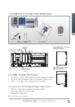
Страница 3: ... in the box P3 Single Channel Wireless System Module Removal Tool Power Connector Panel Mounting Brackets Documentation Coordinator SIDE VIEW WITH 19 RACK MOUNT BRACKET SIDE VIEW WITH PANEL MOUNT BRACKET 140 mm LTD P3 Wireless Run Pause Paused Memory Card Run Error P3 Wireless Module Comms Main Chassis Host Comms Serial Ports for A master station A side P3 CPU Main Module Blanking Module Datalogge...

Страница 4: ... m away from wall surfaces to ensure a clear antenna signal Coordinator ACCEPTABLE 1m or greater 1m or greater INCORRECT CORRECT The Coordinator should be sited free of obstructions and ideally be in line of sight to the first group of actuators The cable run between the Master Station and coordinator must be less than 200 m The Coordinator should be sited clear of metalwork and any other antenna ...

Страница 5: ... survey will indicate the correct orientation required for all modules Correct Antenna Orientation Ideal orientation Alternative orientation where necessary Potential Signal loss Signal loss Communication path required in the system the Coordinator the actuator modules and repeaters if required Each device antenna radiates its signal outwards in a ring If the antenna of the next device is inside t...

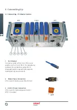
Страница 6: ...y replicate the connections using Port 4 managed switch required that supports rapid spanning tree protocol 2 Mains Power Connectors CPU A and B Mains power 85 263 VAC 3 24 VDC Power Connectors CPU A and B Optional power 24 VDC PS711 module 1 L E N gnd 2 3 3 1 Connecting P3 Master Station PS710 PS731 2 PS710 4 5 ...

Страница 7: ... CPU A port 2 and another to CPU B port 2 on hot standby systems 5 For RS485 Serial Data Connect a cable to CPU A port 1 The system automatically links the connection to port 1 on CPU B Note See page 13 for port defaults 1 2 3 4 5 6 7 8 9 9 way Female D Type RS232 Connections Signal Common Data into P3 Data out from P3 Alarm Emergency Shutdown PS710 CONNECTOR 1 2 3 4 5 9 way Female D Type RS485 Co...

Страница 8: ...8 3 2 Connecting P3 Master Station to Coordinator PS721 PS722 Coordinator Connector 2 3 4 5 6 7 8 1 3 Connecting Up ...

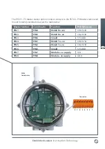
Страница 9: ...mount module coordinator as per the table below Master Station Coordinator Function PCB Reference PIN1 PIN4 RS422 Rx ve CHAN 2A PIN2 PIN5 RS422 Rx ve CHAN 2B PIN3 PIN6 Shield SYSGND PIN4 PIN1 RS422 Tx ve CHAN 1A PIN5 PIN2 RS422 Tx ve CHAN 1B PIN6 PIN3 Shield SYSGND PIN7 PIN7 Module ve supply VIN PIN8 PIN8 Module ve supply GND Connector 2 3 4 5 6 7 8 1 ...

Страница 10: ...s modules Larger network distances are covered as each device acts as a repeater passing signals onwards to other devices Network structure Mesh Channels available 16 Security AES Encryption and anti spoofing Power 10 mW default Potential for 100 mW if location allows REPEATER WMA WMA WMA Wireless Coordinator WMA Wireless Modbus Adaptor Pakscan P3 Wireless only network 4 1 Pakscan P3 specification...

Страница 11: ...l communication route between P3 Wireless coordinator A and actuator wireless module B A B P3 Wireless Device actuator module or repeater P3 Wireless Coordinator Used route Potential routes A Communication route when two wireless devices actuators are off line A B P3 Wireless Device actuator module or repeater P3 Wireless Coordinator Used route Potential routes A The red path between node 1 and no...

Страница 12: ... the menu of the displays returning to the previous screen viewed NEXT only functions if there is more data to show than fits on the screen as depicted by the small arrows on the right side of the screen Arrow keys allow active items within a page display to be highlighted and change a numeric value 6 Setting Up using local HMI ...

Страница 13: ...work AES Key 0F 15 71 C9 47 D9 E8 59 0C B7 AD D6 AF 7F 67 98 Actuator Wireless 300 Module Address Security PIN PIN disabled Control Permit Serial Port 1 Enabled Serial Port 2 Enabled Ethernet Enabled Webpage Disabled Keypad Enabled ESD Serial ESD Disabled Ethernet ESD Disabled Webpage ESD Disabled Hardwired ESD Disabled Keypad Disabled M S Settings Port 1 Standby Mode Passive Port 2 Standby Mode P...

Страница 14: ...an address of 10 200 1 3 and a subnet mask of 255 255 255 0 click on the OK button and the window will close Click OK on the Local Area Connection Properties window and then Close the status window the Network Connections window and the Control Panel Reboot the laptop PC to ensure that the new settings take effect Connect the cable between the laptop PC and the master station front connector Acces...

Страница 15: ...on page 13 The PAN ID AES key and Channel number of the master station can be set using the HMI screens on the master station or using the in built web pages Once the master station has been set up the wireless actuator modules can be powered up and set up with the infra red setting tool If the master station settings are different from the default as recommended none of the modules will appear at...

Страница 16: ...demarks Published and produced in the UK by Rotork Controls Limited POWTG0211 www rotork com A full listing of our worldwide sales and service network is available on our website UK Rotork plc tel 44 0 1225 733200 fax 44 0 1225 333467 email mail rotork com USA Rotork Controls Inc tel 1 585 247 2304 fax 1 585 247 2308 email info rotork com Electric Actuators and Control Systems Fluid Power Actuator...

Отзывы: