ENGLISH
13
Setting the off-set:
press the “+“ and “-“ button at the same time. The heater element can
subse-quently be calibrated using one of these buttons and an external temperature
measuring instrument.
If the heater element displays a smaller value than that on the external temperature measuring
instrument then the difference must be adjusted using the “+“ button. For indicated values in
the other direction adjust the difference using the “-“ button. If “Er1“ appears it means that the
elec-
tronics are defective. “Er2“ means that the resistance thermometer is defective or not
connected.
Very hot
– Do not touch! The heating element can reach a temperature of
approx.290°C!
3.2.2 Preparations for welding
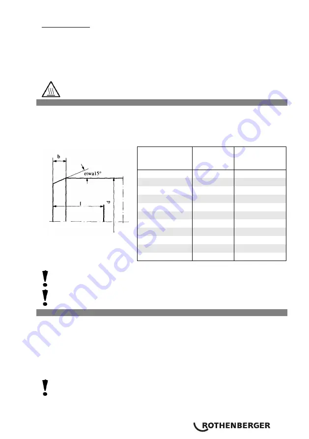
The end of the pipe is to be chamfered as shown in
fig 1
and set out in
Table 1
.
The connection area of the pipe is to be machined as specified by the manufacturer of the
shaped piece.
Make the insertion depth at the end of the pipe over a distance as set out in table 1.
The inside of the shaped piece is to be cleaned thoroughly with a degreasing agent
(for example methylated spirits) and a non-fibrous paper.
Check weather conditions!
3.2.3
Welding
Move the pipe and shaped piece quickly and axially to the mark on the heating arbour and
jack fitted on the heating element and fix them in place.
Keep them secure for the heating time as shown in tables 2-4.
After the elapse of the heating time, pull the pipe and shaped pipe out of the heating
arbour and jack quickly and push them together up to the mark immediately without
turning them (positioning time shown in tables 2-4).
Hold the connection tight for the time shown in tables 2-4 and then allow it to cool.
The weld must not be stressed by further installation work until after the elapse of
the cooling time!
After each weld the heating arbour and jack should be cleaned with non-fibrous paper
and, if necessary, methylated spirits.
Pipe diameter
Pipe chamfer
Insertion depth
PE, PP, PVDF
PE, PP, PVDF
PE, PP, PVDF
d (mm)
b (mm)
l (mm)
16
2
13
20
2
14
25
2
16
32
2
18
40
2
20
50
2
23
63
3
27
75
3
31
90
3
35
110
3
41
125
3
46
fig 1
Table 1
Содержание ROWELD HE
Страница 1: ...Bedienungsanleitung Instructions for use ROWELD P 125 ROWELD P 125 www rothenberger com 55546 55321 ...
Страница 2: ...A Overview 6 1 4 5 3 9 2 10 7 8 ...
Страница 18: ...16 7 Schaltplan Wiring diagram ...
Страница 20: ...18 Handgriff mit Elektronik handle incl electr no 1200001064 i2 1200001073 i2 ...
Страница 23: ...21 NOTES ...


