MDR-42
Technical Data
ROTEC technology
- 28 -
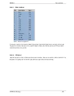
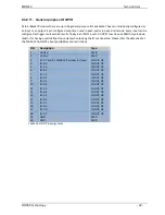
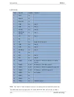
9.4.2.1. VGA interface
PIN
Description
Type
1
Red
Out
2
Green
Out
3
Blue
Out
4
n.c.
-
5
GND
PWR
6
GND
PWR
7
GND
PWR
8
GND
PWR
9
GND
PWR
10
GND
PWR
11
n.c.
-
12
DDC-DATA
IO
13
H-SYNC
OUT
14
V-SYNC
OUT
15
DDC-CLK
OUT
Table 7: VGA Pin assignment
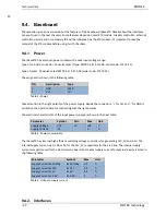
To connect a common VGA monitor rBaseETX board has a 15pin SUB-D high density connector at front side.
The graphic resolutions depends on the used ETX boards. Please refer the manual of your ETX board which
maximal resolutions are possible.
9.4.2.2. Ethernet
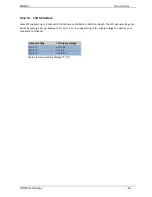
rBaseETX supports a 10-Base-T/100 Base-TX ethernet interfaces. There are two LED for LINK and ACTIVITY. The
left green one signals good link and the right yellow one signals the activity by blinking.
Содержание MDR-42
Страница 1: ...MDR 42 Ruggedized POI PC Display User Manual you ROTEC ...
Страница 2: ......
Страница 14: ...MDR 42 Important Safety Information ROTEC technology 12 ...
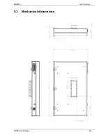
Страница 28: ...MDR 42 Technical Data ROTEC technology 26 9 3 Mechanical dimensions ...
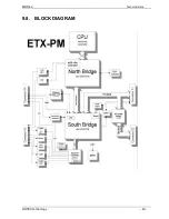
Страница 42: ...MDR 42 Technical Data ROTEC technology 40 9 8 BLOCK DIAGRAM ...

