2.
Use the
Input
knob to select the input that you
want to assign a TSL ID to. Click the
TSL
Address
button for the input you want to assign
a TSL ID to.
3.
Use the
TSLAdr
knob to select the TSL ID that
you want to assign to the selected input. Click
TSL ID number that you want to assign to the
selected input BNC.
4.
Use the
TSLTly
knob to Click the
TSL Tally
button and select how the sources are tallied and
which mnemonic name is use.
•
Off
— TSL tally information for the selected
ID is ignored. TSL mnemonic source names
are used.
•
On
— source tallied on the MultiViewer based
on the TSL input. TSL mnemonic source
names are used.
•
TallyTally Only
— source tallied on the
MultiViewer based on the TSL input. TSL
mnemonic source names are not used.
Note:
If a TSL ID is assigned to a source, the switcher
overwrites the source name on the MultiViewer and
mnemonics with the TSL name. If there is no TSL name, or it
has not been received yet, the source name is blank. For the
labels on the MultiViewer, a combination of the TSL name and
switcher source name are used. The new TSL name is passed
from the switcher to any downstream TSL devices.
Control Panel Button Inserts
Insert films can be installed into most buttons on the
control panel. Insert films allow you to label specific
source buttons, control buttons, or replace the default
button names with those of a different language.
Button insert templates can be downloaded from Ross
Video.
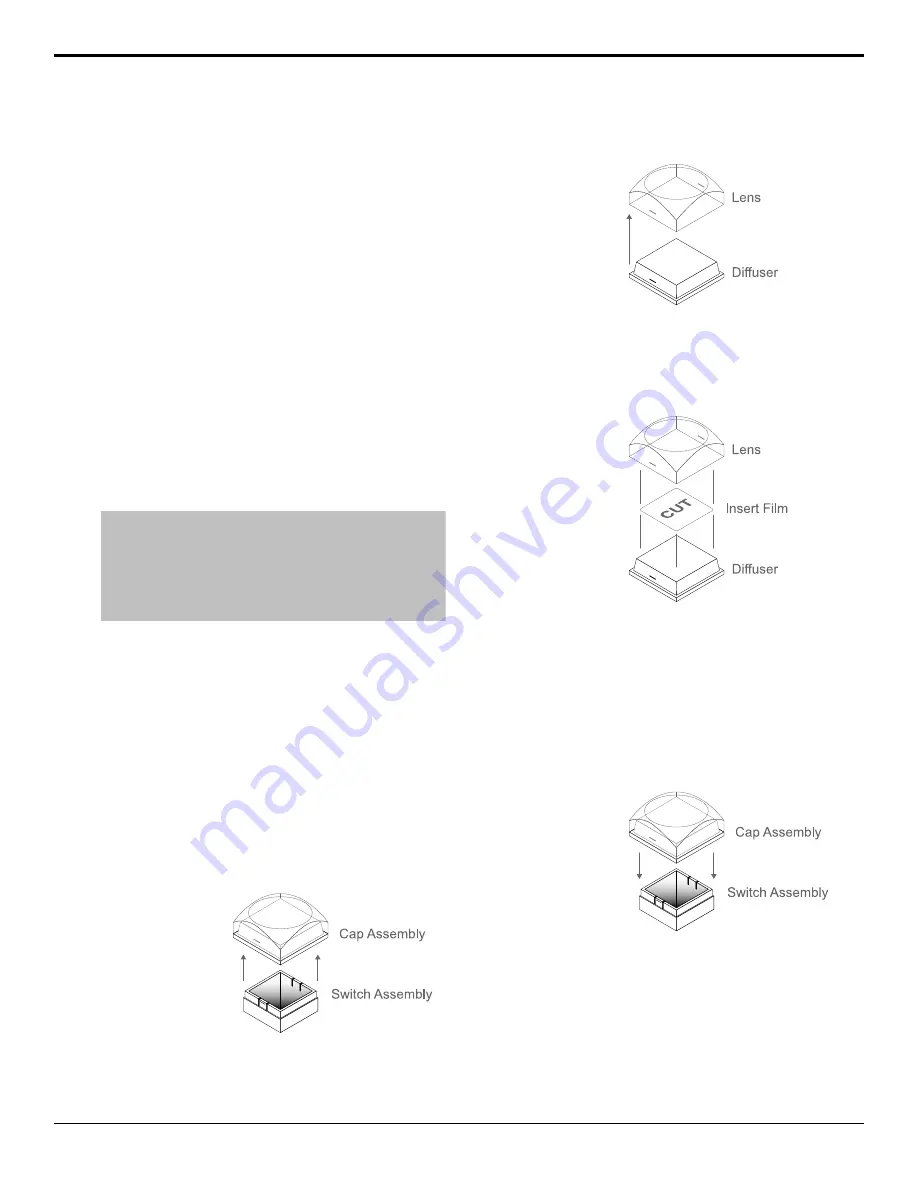
To Install a Button Insert
1.
Remove the Cap Assembly from the Switch
Assembly by grasping it firmly and pulling away
from the control panel surface.
Figure 3: Removing Cap Assembly
2.
Remove the Lens from the Diffuser using a
common end micro screwdriver.
Figure 4: Removing Lens from Diffuser
3.
Place the Insert Film into the Lens so the readable
side is facing up. The notches on the sides of the
Lens must be at the sides of the text on the Insert
Film.
Figure 5: Inserting Film
4.
Aligning the notches on the sides of the Lens and
Diffuser, press the Lens and Diffuser together until
they click.
5.
Aligning the notches on the sides of the Cap
Assembly to the tabs on the side of the Switch
Assembly, press Cap Assembly down onto the
Switch Assembly with a rolling motion until they
click together.
Figure 6: Removing Lens from Diffuser
Bus Maps
Any video input can be mapped to any source button
on the control panel using a bus map. There is an
editable bus map and a fixed, default, bus map, that
can be applied to all MEs on the switcher. Each source
button can have two inputs assigned (a standard source
and a shifted source).
22
• Video Input Setup — Carbonite Black Setup Manual (v14.0)
Содержание Carbonite Black
Страница 1: ...Carbonite Black Setup Manual v14 0 ...


