ACO-2200 User Guide (v5.0)
Operating Basics • 25
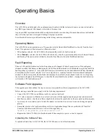
Operating Basics
Overview
The ACO-2200 can be thought of as an automatic multi-pole switch that actuates whenever an error is detected in
any BNC signal channel. All channels will switch at the same time.
Any unused BNC input channel should be configured to disable error checking. If unused channels are not disabled,
they will always produce error signals leading to improper operation.
Error threshold levels are pre-defined during initial testing, and are not adjustable.
Operating Modes
The ACO-2200 can be operated in one of two modes, selected from within DashBoard or directly from the Front
Panel. The options are either Automatic or Manual control.
• When
Auto
is selected, the ACO-2200 will automatically switch if a fault is detected.
• When
Manual
is selected, the ACO-2200 will switch only when the operator manually selects between Primary
and Backup. This can be achieved directly from the Front Panel or from the DashBoard interface.
Fault Reporting
There is LCD and LED indication for fault reporting on all channels. If a fault occurs in one of the configured
channels on either the Primary or Backup input, the LCD and LED indicators will illuminate to report the fault. The
fault reporting is persistent, i.e. even if the fault is only an intermittent one, the fault indicator will stay illuminated.
If more than one fault exists, only the “first” one is reported, i.e. counting from the lowest numbered configured
channel. As faults are repaired, the fault indicator displays the next faulty input/channel in the list, etc. Repairing
the last fault will update the LCD display to show that the [last] fault has been fixed - clearing the fault indication
will turn the LCD fault indication off.
Software Field Upgrades
This upgrade procedure outlines the steps necessary to upgrade the software programmed on the ACO-2200.
Before starting, ensure that you comply with the following requirements:
• Connect the ACO-2200 via an Ethernet cable to your local network;
• A PC, also connected via Ethernet to your local network, with the supplied update program(s) and associated
data file(s) available - ideally, data file(s) should be located in the same folder as the associated update program;
• A power-cycle is required as part of a data file update - ensure that the unit is not in service during the update
process.
• Ensure that you have the Application Image software. Application Image files are prefixed with “ArmFile”.
Usually a load address and software version will be appended, e.g.
“
ArmFile_<load_address>_<software-version>.ata
”.
• Requires that the ACO-2200 is in Bootload mode. When complete, a power re-boot is required.
Uploading the Software Files
To upload software files to a ACO-2200, the ACO-2200 needs to be in Bootload mode.
Содержание ACO-2200
Страница 1: ...ACO 2200 User Guide...
Страница 36: ...36 Technical Specifications ACO 2200 User Guide v5 0...
Страница 42: ...42 Glossary ACO 2200 User Guide v5 0...


