background image

25

INSTRUCTIONS FOR THE INSTALLER


21

Installation using flexible connection 

As  an  option,  the  cooker  may  be  installed  with  a 

flexible  connection  hose,  which  complies  with  AS/

NZS  1869  (AGA Approved),  10  mm  ID,  class  B  or 

D, Minimum 1000 mm - Maximum 1200 mm, as an 

alternative connection.

•  All cookers offer left or right hand connection. The 

manifold  has  a  flat  flair  over  which  is  inserted  a 

screw nut male 

½”

 gas (fig 21A).

•  An  isolating  tap  and  pressure  regulator  must  be 

fixed to the rear wall and the flexible pipe attached 

by means of a union connector. 

•  The  gas  connection  and  isolating  tap  must  be 

accessible to a service person or inspector.

• 

The hose assembly must be installed in accordance 

with AS5601 for a high level connection. The hose 

should  not  be  subjected  to  abrasion,  kinking  or 

permanent deformation and should be able to be 

inspected along its entire length. Unions compatible 

with the hose fittings must be used and connections 

tested  for  gas  leaks.  The  fixed  consumer  piping 

outlet  should  be  at  approximately  the  same 

height  as  the  cooker  connection  point,  pointing 

downwards.

• 

The  hose  should  be  clear  of  the  floor  when  the 

cooker is in the installed position. The hose restraint 

chain  supplied  should  be  anchored  to  the  lower 

hook  fixed  to  the  wall  so  that  the  chain  prevents 

strain on the hose connections when the cooker is 

pulled forward.

• 

Before Leaving - Check all connections for gas leaks 

with soap and water. 

DO NOT

 use a naked flame for 

detecting leaks.  Ignite all burners both individually 

and concurrently to ensure correct operation of gas 

valves, burners and ignition. Turn gas taps to low 

flame position and observe stability of the flame for 

each  burner  individually  and  concurrently.    When 

satisfied,  please  instruct  the  user  on  the  correct 

method of operation. In case the appliance fails to 

operate correctly after all checks have been carried 

out, refer to the authorised service provider in your 

area.

GAS CONNECTION

This  appliance  shall  be  installed  only  by  authorised 

personnel  and  in  accordance  with  the  manufacturer’s 

installation  instructions,  local  gas  fitting  regulations, 

municipal  building  codes,  water  supply  regulations, 

electrical wiring regulations, AS 5601 - Gas Installations 

and any other statutory regulations.

The appliance is adjusted to work at gas indicated on the 

label which is applied on the glass-window of the oven 

door and on the cooker packing.

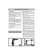
Installation for Natural gas

Connected regulator (B) to fitting (A) which is then fitted to 

elbow (F). Ensure arrow on regulator point in the direction 

shown.  Fitting  (D)  to  be  supplied  by  installer  (fig.  21). 

Adjust regulator to give test-point pressure given on data 

label 

(see on 

TECHNICAL FEATURES

  paragraph)

,


with one large or one medium burner alight at maximum.

Position of Regulator (fig. 21)

The stove must be installed on legs, a gas pipe between 

fitting (A) and (B) will allow location of the regulator (B) 

underneath the stove for adjustment and maintenance

Installation for Propane Gas

Connect by using a copper pipe starting, from the threaded 

fitting of elbow (F) .

Note: When the regulator is fitted at the rear of 

the cooker at least 60 mm clearance is required.

21A

Содержание RR48DF-1-SS

Страница 1: ...Model RR48DF 1 SS Manual Use Care Installation ...

Страница 2: ...at the end of its useful life It must therefore be delivered to a waste recycling centre specifically for electric and electronic equipment or returned to the retailer at the moment of purchase of a new equivalent appliance The user is responsible for delivering the appliance to the appropriate collection centre at the end of its useful life Failure to do so may result in a fine as provided for by...

Страница 3: ...rsonnel For this reason we recommend you always contact our Service Centre specifying the brand the model its serial number and type of problem you are facing with it All data related to your appliance are printed on the data label affixed on the appliance as well as on its original packaging A duplicate data label is contained in this booklet also Please attach this label on the handbook or to an...

Страница 4: ...er and as such dangerous The manufacturer cannot be held responsible for any damage to persons or property resulting from an incorrect installation maintenance or use of the appliance Once the packaging has been removed from the outer surfaces and the various inner parts thoroughly check that the appliance is in perfect condition If you have any doubts do not use the appliance and call in an autho...

Страница 5: ...he first time ensure the oven is empty and its door closed heat the oven at maximum temperature for two hours This will allow the protective coating on the interior of the oven to be burnt off and dissipate the associated smells Ensure adequate ventilation in the kitchen whilst burning off and don t be alarmed by a little bit of smoke during this process When you insert the oven shelf be sure that...

Страница 6: ...ing the lid Not suitable for installation or operation with aftermarket lids or covers Avoid using the oven as a larder or as a saucepan cupboard when you are not using it for cooking if the oven is turned on accidentally it could cause damage and accidents If you are using an electrical socket near the appliance make sure that the cables are not touching the cooker and are far enough away from al...

Страница 7: ...The left oven cavity which is the biggest features of oven natural or forced convection and makes all types of cooking possible The right oven cavity which is the smallest features of oven natural convection with electric grill The oven walls of the two cavity are fitted with various guide bars fig 1 on which the following accessories can be placed fig 2 Oven shelf Ensure shelf is located with dis...

Страница 8: ...ifferent oven temperature values Grill heating element on A B C D OVEN THERMOSTAT KNOB C LEFT CAVITY By turning the oven knob clockwise you will find the different oven temperature values from 50 C to Maxi OVEN MULTIFUNCTION SELECTOR KNOB D LEFT CAVITY By turning the knob to the right or to the left you will find the following symbols 0 Oven off Oven light on which stays on for all functions Fan o...

Страница 9: ...a big range of different temperatures RED WARNING LIGHT If present when lit it indicates that one or more of the hob electric plates is on if the hob is mixed or electric or one of the oven electric components YELLOW WARNING LIGHT indicates the operation of right oven When lit it indicates that either the electric oven or electric grill is working While the oven is being used the light will switch...

Страница 10: ... of the set time the buzzer will start and the symbol A flashes To turn off the buzzer press MODE button Now the oven is off Keep pressed for some seconds simultaneously and buttons or just MODE button and the symbol is illuminated 3 Fully automatic program with Duration and End time Select with and buttons the duration and the end time The time of the day turns off symbol A and End flash Symbol t...

Страница 11: ...ways use pans with lids fig 3 When the boiling point is reached it is best to turn the knob to the Low position Avoid using over sized pans that may radiate excessive heat and cause damage to surrounding surfaces such as bench tops and glass lid Do not place anything e g flame tamer asbestos mat between pan and pan support as serious damage to the appliance may result fig 4 Locate pan centrally ov...

Страница 12: ...gloves when placing or removing pans from the oven or use the handle D fig 2 provided Hook the handle to the edge of the tray and pull it out slightly lifting it as you do so WARNING Accessible parts may become hot during use To avoid burns young children should be kept away When inserting or removing food from the oven check that excess juices do not overflow onto the oven base oils and fats are ...

Страница 13: ...from the top and bottom This type of baking is ideal for all types of food meat fish bread pizza cakes GRILL COOKING Turn the commutator thermostat knob on the symbol The top heating element is turned on and it distributes heat directly onto the food Besides grilling it can be used to obtain a golden finish onto cooked foods or to toast your bread slices The grill function automatically activates ...

Страница 14: ...nd its heat is distributed by the fan This function is particularly recommended to defrost and warm up ready made meals FAN REAR HEATING COMBINED COOKING Turn the selector knob to the symbol and set the thermostat to the desired temperature then place your food the oven If oven needs pre heating wait till the thermostat yellow led turns off before placing foods inside it This function activates th...

Страница 15: ... sprinkle it with flour or bread crumbs If the biscuits will not come away from the baking tray put the tray back in the oven for a while and lift the biscuits up before they cool The next time use a sheet of baking parchment to prevent this happening again Meat If when cooking meat the time needed is more than 40 minutes turn the oven off 10 minutes before the end of cooking time to exploit the r...

Страница 16: ...25 PATISSERY Biscuits in general Shortcrust pastry Victoria sponge 2 2 2 190 200 200 20 20 40 45 CAKES FLANS Angel Cake Sponge Fruit Cake Chocolate Cake 0 8 0 8 0 8 1 1 2 1 2 190 200 200 50 65 45 Values indicated in the tables temperatures and cooking times are approximate and may vary according to each person s cooking habits GRILLING TIMETABLE FOODS Weight kg Position of the oven shelf from the ...

Страница 17: ...e 0 8 2 2 2 190 200 200 15 20 40 45 170 190 190 200 190 200 15 20 40 45 CAKES Angel cake Fruit cake Chocolate cake 0 8 0 8 0 8 2 2 2 190 200 200 52 65 45 170 190 190 200 190 200 45 65 45 The values given in the tables temperatures and cooking times are approximate and may vary according to each person s cooking habits This table gives cooking times on only one shelf If you are cooking with a fan o...

Страница 18: ...the glass fig 10 ATTENTION This operation can be done also with the door fitted on appliance but in this way pay attention that when the glass is pull upwards the force of the hinges can close the door roughly LOCK AT LEAST ONE HINGE fig 12 CLEANING AND MAINTENANCE Prior to any maintenance work or cleaning disconnect the appliance from the electricity mains Do not wash the parts if they are still ...

Страница 19: ...o free sector To reassemble proceed in the reverse order paying attention to the correct position of sectors REPLACING THE OVEN LAMP Ensure the appliance is switched off before replacing the lamp to avoid the possibility of electric shock In the event one or both oven lamps need replacing the new lamps must comply with the following requisites 15 W 230 V 50 Hz E 14 and must be resistant to high te...

Страница 20: ...is to be placed directly on the floor and should not be mounted on a base The walls adjacent to and surrounding the appliances must be able to withstand an temperature of 95 C The installation of all gas and combi appliances must comply with the standards in force This appliance is not connected to a flue for discharge of the combustion products therefore it must be connected in compliance with th...

Страница 21: ...the room The natural flow of air must be direct through permanent apertures in the walls of the room that open directly to the outside with a minimum cross section of 100 cm2 fig 15 These apertures must be positioned in such a way as not to be obstructed Indirect ventilation is also allowed by taking air from adjacent rooms to the one to be ventilated and must comply with all current standards AIR...

Страница 22: ...nstallation engaged in the rear lower part of sides of the range A CHILD OR ADULT CAN TIP THE RANGE AND BE KILLED INSTALL THE ANTI TIP DEVICE PACKED WITH RANGE TO THE STRUCTURE AND THE RANGE VERIFY THE ANTI TIP DEVICE HAS BEEN PROPERLY INSTALLED AND ENGAGED ENGAGE THE RANGE TO THE ANTI TIP DEVICE BY SLIDING THE RANGE TOWARDS THE WALL UNTIL THE BRACKETS FIXED ON RANGE ARE WELL INTO THE HOLES OF THE...

Страница 23: ...lide the range towards the wall until the brackets A are well into the holes in the brackets B GROUND FIXING BRACKETS Adjust the range height by regulating the feet until you reach the desired cooktop height Fix the components A to the cooker Fix the components C to the ground according to width width the range Fix C to B with the screws keeping the distance of the components A Repeat the same seq...

Страница 24: ...the law All responsibility is disclaimed if this is not complied with The plug and socket or the multipolar switch must be accessible after installation of the appliance The power cable must be laid so that no parts of it ever reach a temperature of 75 C For connecting do not use adapters or shunts as they could cause false contacts resulting in hazardous overheating INSTRUCTIONS FOR THE INSTALLER...

Страница 25: ...Ignite all burners both individually and concurrently to ensure correct operation of gas valves burners and ignition Turn gas taps to low flame position and observe stability of the flame for each burner individually and concurrently When satisfied please instruct the user on the correct method of operation In case the appliance fails to operate correctly after all checks have been carried out ref...

Страница 26: ...with flame failure device the adjustment screw V is over or on the side of the stem fig 22 Check that the flame does not go out when the knob is sharply switched from the Full on to Reduced rate positions INSTRUCTIONS FOR THE INSTALLER CONVERSIONS REPLACING THE INJECTORS Our burners can be adapted to different types of gas by simply installing the injectors suitable for the gas you want to use To ...

Страница 27: ...ove it Remove the hob unscrewing rear fixing screws Vs fig 24 which lock the hob at the supports S Unscrew the nuts D of the gas aluminium pipes and pull out the thermocouple quick connectors F fig 26 Unscrew the screws Vt fig 25 which lock the crosspieces l Unscrew the screws Vb fig 25 which unite the the bridles of the taps to the front frame Make to slip the ramp toward the back part and unscre...

Страница 28: ... lamp please refer to instructions on REPLACING THE OVEN LAMP paragraph To change the lamp holder P type 1 force the tabs of blockage M and take the lamp holder toward the outside of the oven fig 27 To replace the ignition generator remove the left side panel of the appliance To change the thermostat commutators or hob heating elements the work top has to be removed 27 CHANGING THE FLEXIBLE GAS HO...

Страница 29: ...mmer accessory is on the manual position and then repeat the operations described in the manual The thermostats are not working Call our Service Centre The electric thermostat warning lights do not switch on during use Turn the thermostat round to a hotter temperature Turn the selector round to a different function The oven lights does not switch on Make sure the lamp is firmly screwed in place Bu...

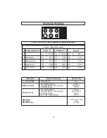
Страница 30: ...rill heating element Rear circular heating element 2100 W 2100 W 2000 2200 W 2000 2200 W 2000 W 2000 W 3000 W 3000 W Oven lamp Cooling fan Rear Fan motor 15 W E 14 T 300 12 W 25 29 W BURNER DISPOSITION AND HOB BURNER TECHNICAL DATA TABLE Burners injectors and volume N BURNER DENOMINATION Natural 4 LP Propane 11 By pass Inj W BTU h Inj W BTU h Ø W BTU h 4 Small burner 90 3400 54 3500 28 1100 3 Medi...

Страница 31: ...SPACE FOR DATA LABEL ...

Страница 32: ...RomA PROFESSIONAL Maple Distributing 6200 Maple Avenue Dallas Texas 75235 833 876 4600 mapledistributing com support romaappliances com 461308685 000 12 2019 ...

Отзывы: