background image

Network Settings

18

Connecting to a Wi-Fi Router by WPS

This connects the unit and Wi-Fi router by using WPS.
WPS” is a feature that makes it easy to connect to a Wi-Fi router 

and make security-related settings.

MEMO


5

The Wi-Fi router you’re using must support WPS.


5

When a WPS connection is made to a Wi-Fi router, the 

connection information is saved in memory, and thereafter the 

connection is established automatically.

1. 

Insert the optional wireless USB adaptor into the unit’s 

USB WLAN ADAPTOR port.

For the wireless USB adaptor, use the ONKYO UWF-1 or Roland 

WNA1100-RL.

2. 

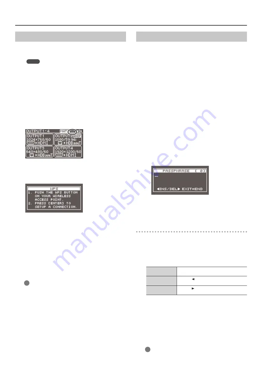
Wait until the icon shown below appears at the upper 

right of the unit’s display.

3. 

Use the [MENU] button to select “WIRELESS LAN” 

g


“WPS,” then press the [VALUE] dial.

The “WPS” popup appears.

4. 

Enable WPS on the Wi-Fi router (e.g., press the router’s WPS 

button).

*  To enable WPS on the Wi-Fi router, refer to the documentation 

for the router.

5. 

Press the [VALUE] dial.

The WPS connection is established.
When connection is successful, the “WPS” popup disappears and 

the unit returns to the WIRELESS LAN menu.

6. 

Press the [MENU] button to quit the menu.

7. 

Connect the iPad and the Wi-Fi router.

On the iPad, tap “Settings” 

g

 “Wi-Fi,” make sure Wi-Fi is turned 

on, then at “Choose a Network,” select the Wi-Fi router to 

which the unit is connected.

Selecting and Connecting to a Wi-Fi Router

From the list of Wi-Fi access points, select the Wi-Fi router where 

you want to connect the unit.

*  The 802.11g/n (2.4-GHz) wireless protocols and WPS and WPS2 

authentication methods are supported.

*  For information on how to operate the Wi-Fi router, refer to the 

router’s documentation.

1. 

Insert the optional wireless USB adaptor into the unit’s 

USB WLAN ADAPTOR port.

For the wireless USB adaptor, use the ONKYO UWF-1 or Roland 

WNA1100-RL.

2. 

Use the [MENU] button to select “WIRELESS LAN” 

g


“ACCESS POINT,” then press the [VALUE] dial.

The “ACCESS POINT” popup appears.


5

The number of the currently selected Wi-Fi router is highlighted.


5

Names that use other than single-byte alphanumeric characters 

are not displayed correctly.

3. 

Select the Wi-Fi router you want to connect to and press 

the [VALUE] dial.


5

When the Wi-Fi router is one you’re connecting to for the 

first time
The “PASSPHRASE” popup appears. Go on to step 4.


5

When the Wi-Fi router is one that you’ve connected to in the 

past
The connection is made as soon as you select the Wi-Fi router. 

When a successful connection is made, the unit returns to the 

WIRELESS LAN menu. Go on to step 7.

Entering Security Data

*  This procedure is necessary only when the Wi-Fi router is one 

you’re connecting to for the first time.

4. 

Enter the security data (passphrase) for the Wi-Fi router.

Pressing the [VALUE] dial lets you change the character at the 

cursor location. Turn the [VALUE] dial to change the character, then 

press the [VALUE] dial to apply the change.

Moving the cursor

Turn the [VALUE] dial. The cursor moves forward or 
backward.

Inserting a character

Press the [   ] button. The same character as the 
one just before the cursor location is inserted.

Deleting a character

Press the [   ] button. The character at the cursor 
location is deleted.

5. 

When you’ve finished entering the text, press the [EXIT] 

button.

6. 

Check the message and press the [VALUE] dial.

(If you want to quit, press the [EXIT] button.)
When a successful connection is made, the unit returns to the 

WIRELESS LAN menu.

7. 

Press the [MENU] button to quit the menu.

8. 

Connect the iPad and the Wi-Fi router.

On the iPad, tap “Settings” 

g

 “Wi-Fi,” make sure Wi-Fi is turned 

on, then at “Choose a Network,” select the Wi-Fi router to 

which the unit is connected.

Содержание XS-82H

Страница 1: ...system program is at the most recent version For information on available upgrades for the system program see the Roland website http proav roland com You can check the version of the system program b...

Страница 2: ...ode 17 Connecting to a Wi Fi Router by WPS 18 Selecting and Connecting to a Wi Fi Router 18 Setting the Wireless ID 19 Checking the Wi Fi Information 19 Making a Wired Connection to the Wi Fi Router 1...

Страница 3: ...the horizontal position of input video POSITION V 1200 0 1200 pixel This adjusts the vertical position of input video FLIP VERTICAL 7 OFF ON Setting this to ON flips input video vertically BRIGHTNESS...

Страница 4: ...000 pixel This adjusts the vertical cropping width BRIGHTNESS 128 0 127 This adjusts the brightness of output video CONTRAST 128 0 127 This adjusts the contrast of output video SATURATION 128 0 127 Th...

Страница 5: ...TPUT 3 OUTPUT 4 MATRIX settable settable settable settable MULTI 2 SPAN 2 2 x PGM PST settable settable MULTI 3 SPAN 3 3 x PGM PST settable DISSOLVE 1 settable settable PGM PST settable settable setta...

Страница 6: ...output channel are displayed ON or hidden OFF Separately adjusting the size and position of the window for each output channel is not possible 15 Effective when MODE is set to a value from MULTI 2 to...

Страница 7: ...Audio that does not reach the threshold level is removed RELEASE 30 ms 500 ms 5000 ms This adjusts the length of time until the gate effect ends after audio falls below the threshold COMPRESSOR DUCKI...

Страница 8: ...z 10 0 kHz This adjusts the center frequency when changing the sound quality in the low midrange band LOW MID Q 0 50 1 00 16 0 This adjusts the bandwidth when boosting or attenuating the low midrange...

Страница 9: ...nder VIDEO OUTPUT is set to ON the output video is not interrupted during mode switching For more information on output modes refer to the Owner s Manual p 22 and Functions Added in Ver 2 0 Ver 3 0 19...

Страница 10: ...PUT connector selected using EDIT COPY OUTPUT 21 The DATA1 8 settings are not saved at individual presets Only a single set is saved in the unit After settings for menu items have been made the new va...

Страница 11: ...ANUALLY WIRELESS LAN Menu item Value Description 2nd level 3rd level ACCESS POINT ENTER Pressing the VALUE dial displays the ACCESS POINT popup From the list of wireless LAN access points you select t...

Страница 12: ...ishes flip function OUT1 LINKED CH 25 OUTPUT1 OUTPUT4 This varies according to model This sets the output channel selection with which switching of OUTPUT1 is interlinked when the cross point selectio...

Страница 13: ...or outputting commands STARTUP This outputs commands at unit startup PRESET1 32 This outputs commands when a preset is recalled TYPE Settings and CommandValues Value Command value Description EPSON Po...

Страница 14: ...OFF ON OFF buttons CROSS OUTPUT1 CROSS OUTPUT4 This varies according to model OFF ON Cross point selection buttons for each respective OUTPUT row Operation Turns key lock mode on off 1 For KEY LOCK M...

Страница 15: ...This displays format information for the input video DELETE STILL IMAGE 1 4 Selecting a still image save destination from 1 to 4 and pressing the VALUE dial displays the DELETE STILL popup Here you d...

Страница 16: ...er You make a wireless connection between the unit and a Wi Fi router and make a wireless connection to the iPad via the router g Connecting to a Wi Fi Router by WPS p 18 g Selecting and Connecting to...

Страница 17: ...or the wireless USB adaptor use the ONKYO UWF 1 or Roland WNA1100 RL 2 Use the MENU button to select WIRELESS LAN then set AD HOC MODE to ON This turns on ad hoc mode 3 From the WIRELESS LAN menu sele...

Страница 18: ...N ADAPTOR port For the wireless USB adaptor use the ONKYO UWF 1 or Roland WNA1100 RL 2 Use the MENU button to select WIRELESS LAN g ACCESS POINT then press the VALUE dial The ACCESS POINT popup appear...

Страница 19: ...router is in effect NOT AVAILABLE No wireless USB adaptor is attached AD HOC In ad hoc mode SSID This displays the SSID IP ADDRESS This displays the IP address SUBNET MASK This displays the subnet mas...

Страница 20: ...T select HDMI 1 to HDMI 4 then make the setting for OUT1 SEND RATE to OUT4 SEND RATE Note This varies according to the model Example of SettingsWhen No Audio Is Output Shown in the figure below When H...

Страница 21: ...successively sending commands to the unit from an external device after each command be sure that ACK is returned before sending the next command Control Using the LAN Port You can use TCP control com...

Страница 22: ...0 CH 1 3 CH 4 b Color space 0 Auto 1 RGB 0 255 2 RGB 16 235 3 YCC 444 4 YCC 422 VOD This sets the signal type for a video output channel VOD a b a Output channel number 0 CH 1 3 CH 4 b DVI D HDMI Sign...

Страница 23: ...G IN8 b Send Rate 0 100 ASC The sets the send level for audio sent to OUTPUT3 ASC a b a Input channel number 0 HDMI IN1 7 HDMI IN8 8 ANALONG IN1 15 ANALOG IN8 b Send Rate 0 100 ASD The sets the send l...

Страница 24: ...6 9 2 480p 4 3 576p 4 3 3 480p 16 9 576p 16 9 4 720 59 94P 5 1080 59 94i 6 1080 59 94P 7 640 x 480 8 800 x 600 9 1024 x 768 10 1280 x 768 11 1280 x 800 12 1366 x 768 13 1280 x 1024 15 1600 x 1200 16 1...

Отзывы: