7-7
Installing Roland
OnSupport
Install Roland OnSupport in reference to the Startup Guide.
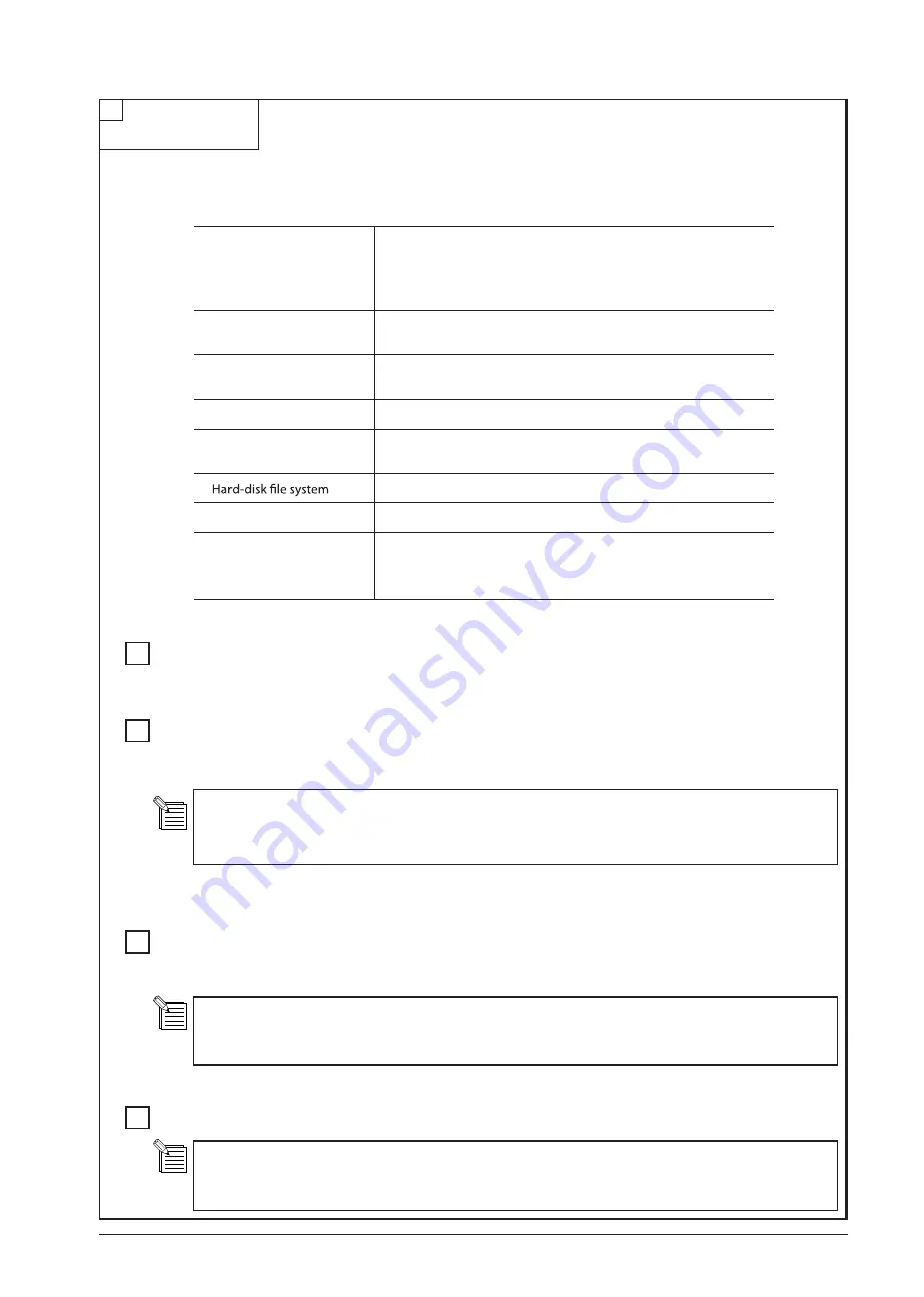
System Requirements
Basic Operations
- How to display OnSupport Help
Environmental Settings (Language/Network)
- Checking the Network Connection
- Setting the E-mail Server
- What is “OnSupport Mail”?
Registering/Loging in/Updating the Account
- Registering the Roland DG Account if the customer accepts it
- How to update OnSupport
Connecting and Managing the Devices
To fully utilize OnSupport, you need to connect your computer to our OnSupport server via the Internet. If your
computer is linked to the Internet, you will enable its connection to our OnSupport server only by installing
OnSupport.
When you register the Roland DG Account (Roland DG ID), you will become able to use OnSupport more
effectively. You are to communicate with our OnSupport server in registering your account.
E-mail address is required.
When you make the management settings, you will become able to use “OnSupport Mail function” and the
“Device Firmware Update function.” To update the firmware, you need to log in OnSupport with the computer
with which you made the management settings.
Operating system (OS)
Windows 7 Professional/Ultimate (32-bit edition)
Windows Vista Business/Ultimate Service Pack 1 (32-bit edition)
Windows Vista Business/Ultimate (32-bit edition)
Windows XP Professional Service Pack 2 or later
Processor
2.0 GHz or faster Pentium 4
(2.0-GHz or faster Core 2 Duo recommended)
Memory (RAM)
512 MB of RAM (1 GB or more recommended)
( For Windows Vista/7, 1 GB ( 2 GB or more recommended) )
Video card and monitor
A resolution of 1,280 x 1,024 or more recommended
Free hard-disk space re-
quired as a working space
40 GB or more recommended
NTFS format
Optical drive
CD-ROM drive
Other requirements
�
Ethernet port
�
Internet connection and web browser
�
Communication environment where you can send e-mails
* For the latest information, see the Roland DG Corp. website (http://www.rolanddg.com).
Содержание VS-300
Страница 49: ...2 4 MAIN BOARD_Arrangement Diagram Soldering Side ...
Страница 59: ...2 14 2 3 SERVO BOARD SERVO BOARD_Arrangement Diagram Component Side It indicates the version of the Board ...
Страница 60: ...2 15 SERVO BOARD_Arrangement Diagram Soldering Side ...
Страница 65: ...2 20 2 4 CARRIAGE BOARD CARRIAGE BOARD_Arrangement Diagram Component Side ...
Страница 68: ...2 23 2 5 SUB BOARD SUB BOARD_Arrangement Diagram Component Side ...
Страница 141: ...3 68 7 8 OFF Dispose of the battery Turn off the Sub Power SW and then turn off the Main Power SW Fix the Chassis Cover ...
Страница 257: ...4 59 22 Fix the Right Side Frame by sliding it from behind to hook the tab as shown in the fig ure ...
Страница 279: ...7 2 Unpacking Manual CD ROM DVD ROM etc ...


