background image

34

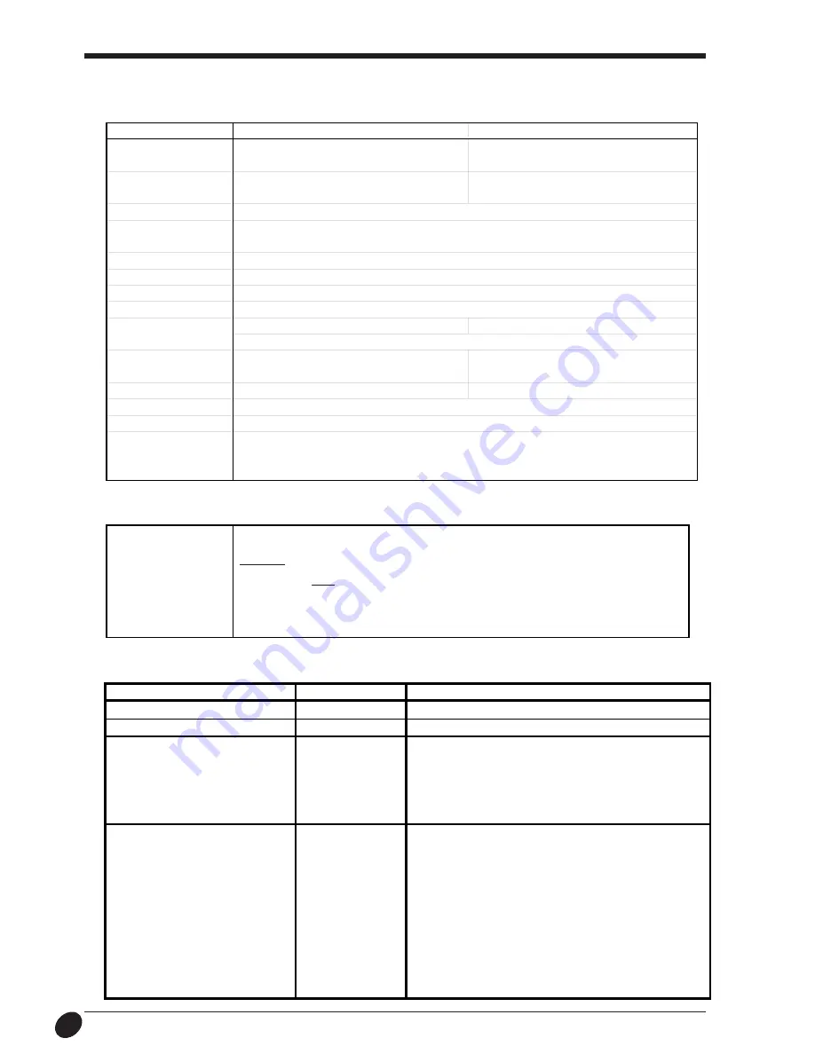
Specification

Option Lists

T y p e

Model Nbr.

C o n t e n t s

Cemented Carbide Blades

ZEC-U1002

 2 pcs./pkg

Adjustable Depth Blade Holder

XD-CH3

 1 pcs./pkg

Pressurized Oil Based

XD-BPHG

 Holder (with one black refill for test)

Ball-point Pen

XD-3M-BLK

 Replaceable Refill    3 pcs./pkg,  All Black

XD-3M-RED

 Replaceable Refill    3 pcs./pkg,  All Red

XD-3M-BLU

 Replaceable Refill    3 pcs./pkg,  All Blue

XD-3M-GRN

 Replaceable Refill    3 pcs./pkg,  All Green

Thick Water-based

XD-4SPA-WBG

 4 pcs./pkg,  All Black

Fiber Tipped Pens

XD-4SPB-WBG

 4 pcs./pkg,  1 Each Black, Red, Blue, Green

(Line Thickness : 2.0 mm)

XD-4SPC-WBG

 4 pcs./pkg,  1 Each Brown, Purple, Pink, Orange

XD-4SPD-WBG

 4 pcs./pkg,  All Red

XD-4SPE-WBG

 4 pcs./pkg,  All Blue

XD-4SPF-WBG

 4 pcs./pkg,  All Green

XD-4SPG-WBG

 4 pcs./pkg,  All Orange

XD-4SPH-WBG

 4 pcs./pkg,  All Pink

XD-4SPI-WBG

 4 pcs./pkg,  All Brown

XD-4SPJ-WBG

 4 pcs./pkg,  All Purple

Main unit Specification

 [ Parallel ]

Standard

In  compliance with the specification of Centronics

Input signal

STROBE (1BIT), DATA (8BIT)

Output signal

BUSY (1BIT), ACK (1BIT)

I/O signal level

TTL level

Transmission method

Asynchronous

Interface Specification

STX-8

STX-7

Max. cutting area

250 mm (X) x 1000 mm (Y)

160 mm (X) x 1000 mm (Y)


(9-13/16" (X) x 39-5/16" (Y) )

 (6-1/4" (X) x 39-5/16" (Y) )

Acceptable sheet size

Width: 280—305 mm  (11"—12") 

Width: 200—215 mm  (7-13/16"—8-7/16") 

Length: 1100 mm (43-1/4") or less

Length: 1100 mm (43-1/4") or less

Cutting speed

12—40 mm/sec.  (7/16"/sec.—1-9/16"/sec.)

Acceptable material

PVC sheet (0.1 mm (0.00394") or less in thickness, 0.3 mm (0.0118") or less in thickness

 including the backing board).

Control keys

STANDBY key

LED

STANDBY LED

Interface

Parallel (in compliance with the specification of Centronics)

Power consumption

Exclusive AC adapter (DC+12V 1.5 A)

Acoustic noise level

Cutting mode: 50 dB (A) or less

Cutting mode: 47 dB (A) or less

 (According to ISO 7779)

External dimensions

419 mm (W) x 147 mm (D) x 95.5 mm (H) 

317 mm (W) x 147 mm (D) x 95.5 mm (H) 

(16-1/2" (W) x 5-13/16" (D)) x 3-13/16" (H))

(12-1/2" (W) x 5-13/16" (D)) x 3-13/16" (H))

Weight  (unit only)

2 kg  (4.4 lb.)

1.6 kg  (3.5 lb.)

Operation temperature

5—40

°

C  (41—104

°

F)

Operation humidity

35—80 %  (no condensation)

Accessories

Roland Software Package, Blade holder, Blade, AC adapter, Material for test cuts, 

Applicationtape for test cuts, * Sheet setup guide, * Water based fiber tipped pen, * Paper,  

STX-8/7 User's Manual

* Included only with the STX-8.

Содержание Stika Plus STX-8

Страница 1: ...ndows NT 4 0 i486DX or better Pentium 100 MHz or more recommended Memory If you re using Windows 95 8 Mbytes or more 16 Mbytes or more recommended If you re using Windows 98 or Windows NT 4 0 16 Mbyte...

Страница 2: ...is likely to cause harmful interference in which case the user will be required to correct the interference at his own expense Unauthorized changes or modification to this system can void the users au...

Страница 3: ...done is indicated by the design contained within the circle The symbol at left means the power cord plug must be unplugged from the outlet Do not disassemble repair or modify Doing so may lead to fire...

Страница 4: ...the location The configu ration of the AC adapter varies according to regional differences in voltage Please note that the descriptions in this manual are for the 117 V adapter Do not touch the tip of...

Страница 5: ...configuration of the AC adapter varies according to regional differences in voltage Please note that the descriptions in this manual are for the 117 V adapter NOTICE Never install this unit in any of...

Страница 6: ...rials which has curled upward Material with a front edge that is not straight Material that is longer than 1 m 10 cm 43 1 4 Material with left and right edges that are not parallel 3 Load the material...

Страница 7: ...terial that is equal to the length required for cutting plus a margin and load this cut piece on the STX 8 7 for cutting Material cannot be loaded on the STX 8 7 while still attached to the roll Using...

Страница 8: ...the left and right edges may not be perfectly aligned Blade protector Material Sheet setup guide Guide lines 4 Power ON 1 Close the front cover and press the STANDBY key 2 The STANDBY LED lights up a...

Страница 9: ...nd back on Verification The blade leaves faint traces on the backing paper when cutting the cross The sticker cannot easily be peeled off of the backing paper The blade cuts into the backing paper The...

Страница 10: ...e sure to perform a test cut to verify the cutting quality 3 Place the piece of cardboard serving as the cushion on a level surface then lay the material on top of the cardboard Grasp the blade holder...

Страница 11: ...he mouse the on screen arrow mouse pointer also moves Moving the mouse pointer to line up the tip of the pointer with an item on the screen is called pointing Double click Rapidly press and release th...

Страница 12: ...k on the Add Printer icon If you re using Windows 95 or Windows 98 follow the steps below to install the driver The screens shown in these steps are for Windows 95 These screens may differ in places f...

Страница 13: ...nter then click Next If this screen doesn t appear see the next step 6 Click Have Disk 7 Click Browse 8 Click the drop down arrow for Drives then select the CD ROM drive 9 Double click the drivers win...

Страница 14: ...e CD ROM starts After all the files have been copied a printer icon appears in the Printers folder and installation of the driver is complete Remove the CD ROM disk from the CD ROM drive 14 Installing...

Страница 15: ...diately after installing the STIKA PLUS Driver continue from step 2 If you re using the driver for Windows NT no settings are needed The screens shown in these steps are for Windows 95 This help conta...

Страница 16: ...d the driver 10 SALE SALE 1 Click Start and point to Program Then point to Roland Dr STIKA PLUS and click Dr STIKA PLUS Starting the Software 2 The opening screen appears and Dr STIKA PLUS starts From...

Страница 17: ...context sensitive help Click then click the item you wish to know more about 1 Setting the cutting range 1 From the File menu click Print Setup 2 For the STX 8 select Roland STIKA PLUS STX 8 For the...

Страница 18: ...ngs is displayed and click OK When using sheet material other than the included material and making changes in the tool conditions refer to the help for the driver For pen plotting refer to 14 Draft P...

Страница 19: ...k Zoom in Right click Zoom out Creating the Data The fonts that Dr STIKA PLUS can use are limited to the TrueType fonts available for Windows When selecting a font non TrueType fonts are not displayed...

Страница 20: ...the file is to be saved 1 Click 4 Click 11 1 Click then click OK in the dialog box that appears If you wish to make the settings for the cutting conditions again please refer to 10 Creating Data with...

Страница 21: ...ff the power Click Start Click Settings then click Printers 3 For the STX 8 double click the Roland STIKA PLUS STX 8 icon For the STX 7 double click the Roland STIKA STX 7 icon 4 At the Printers menu...

Страница 22: ...can be handy for peeling detailed areas and other hard to peel places 3 Cover evenly with application tape so that no air bubbles are trapped between the tape and the material then transfer the materi...

Страница 23: ...he tool conditions to display the Tools tablet shown at right Select a value from 1 to 8 as the setting Collar After using a pen be sure to remove the pen from the carriage then cap it securely before...

Страница 24: ...should be arranged so that shapes do not overlap Shapes that overlap are suitable for use as cutting data when one shape is completely enclosed within another Editing objects Enlarging shrinking and c...

Страница 25: ...ct then click Properties Editing by changing the numerical values 2 The Object Property dialog box appears Here you can edit the object by entering numerical values The items that can be edited vary a...

Страница 26: ...ines and press the Insert key Deleting a point Click on the point to be de leted Press Delete to delete the point Click the mouse at the location where the new point is to be added A appears at the lo...

Страница 27: ...d in front of the smaller one Select the large circle When an object cannot be selected All objects maintain a certain front to back relationship when they overlap This hierarchy depends on the sequen...

Страница 28: ...symbol Importing a symbol 2 Select the symbol to be used and click Insert 3 The imported symbol appears You can adjust its size and position 1 From the Object menu click Symbol The Symbol dialog box a...

Страница 29: ...2 The clipboard is used to hold data temporarily when it is being copied or cut The clipboard is a standard feature of Windows 95 3 Bitmap data is a data format that represents shapes as a collection...

Страница 30: ...lp ensure attractive results of cutting start with a larger object and reduce it to the desired size 4 When the scanning is finished the scanned data is imported into Dr STIKA PLUS The Preview dialog...

Страница 31: ...In general a higher resolution yields outlining of greater accuracy The optimal resolution varies according to a shape s complexity and size when cut However it takes longer to import high resolution...

Страница 32: ...rom the File menu click Print Setup For Orientation click Landscape then click OK 2 The orientation white portion of the screen changes from portrait to landscape When cutting is actually performed th...

Страница 33: ...The cut length of this line is the length for the cutting range that has been set for the driver Loading material that is shorter than the cutting range may result in the material coming loose Be sure...

Страница 34: ...t Roland DG Corp sales office for replacement of the blade protector Replacement of the blade protector is a charged procedure Cleaning the Blade Holder 8 Flip the material back so that it is face up...

Страница 35: ...off the power to the computer and the STX 8 7 and use a parallel cable to connect the two devices Is the correct type of cable used The type of parallel cable printer cable may vary according to the c...

Страница 36: ...sion method Asynchronous Interface Specification STX 8 STX 7 Max cutting area 250 mm X x 1000 mm Y 160 mm X x 1000 mm Y 9 13 16 X x 39 5 16 Y 6 1 4 X x 39 5 16 Y Acceptable sheet size Width 280 305 mm...

Страница 37: ...not individually licensed to use this Software You may use the Software by one person with using a single computer in which the Software is installed 4 Reproduction You may make one copy of the Softwa...

Отзывы: