Roland SolJet SJ-500 Скачать руководство пользователя страница 44

42

Maintenance

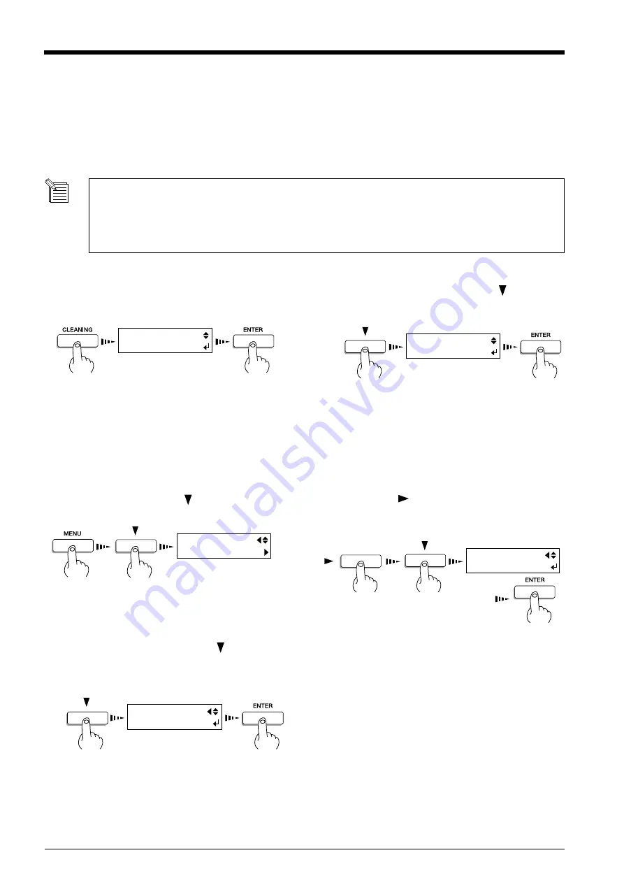
If drop-out persists even after carrying out cleaning several times

Press the [CLEANING] key  to make the following
screen appear on the display.
Press the [ENTER] key, head cleaning starts.

1

When head cleaning ends, press the [     ] key to
display the screen shown in the figure.  Press the
[ENTER] key to start the printing test.

2

Check the printing-test results.
If a problem is found, repeat the cleaning.

3

HEAD CLEANING
START

HEAD CLEANING
TEST PRINT

Press the [MENU] key and [   ] key to make the
following screen appear on the display.

1

Press the [ 

 ] key to make the following screen

appear on the display.
Press the [ENTER] key, head cleaning starts ([POW-
ERFUL]).

2

When head cleaning ends, press the [   ] key to
display the screen shown in the figure.  Press the
[ENTER] key to start the printing test.

3

Refer to “Setup for Printing -- 2 Test  Printing” and
check the printing-test results.
If a problem is found, repeat the cleaning.

(The [NORMAL] menu item for [HEAD CLEAN-
ING] does the same thing as [HEAD CLEANING] -
[START] displayed when the [CLEANING] key is
pressed.)

4

MENU
HEAD CLEANING

HEAD CLEANING
POWERFUL

HEAD CLEANING
TEST PRINT

Cleaning the Printing Heads

Switching on the sub power automatically performs maintenance operations, including cleaning of the printing head.  This means that
there is normally no need to perform cleaning otherwise.
If drop-out occurs with printed images, clean the printing head.
* After cleaning, carry out a printing test.  Load material.

The cleaning causes a certain amount of head wear and also consumes a certain amount of ink, so use should be kept
to a minimum.
[POWERFUL] results in faster head wear and also uses up much ink.  (Performing cleaning from the [POWERFUL]
menu uses up about 57 cc of ink for six colors. This is because the process discharges all ink in the ink tube and
replaces it with fresh ink.)

Содержание SolJet SJ-500

Страница 1: ...ect to change without notice The operation manual and the product have been prepared and tested as much as possible If you find any misprint or error please inform us Roland DG Corp assumes no respons...

Страница 2: ...ave 3 prong grounding plugs and 3 pole receptacles that accept the tool s plug Repair or replace damaged or worn out cord immediately For Canada CLASS A NOTICE This Class A digital apparatus meets all...

Страница 3: ...0 Part Names 23 Front View 23 Rear View 24 Inside the Front Cover 24 Operation Panel 25 Five Modes 26 Setup for Printing 27 1 Loading the Material 28 2 Test Printing 32 3 Setting the Printing Mode and...

Страница 4: ...r be disassembled The symbol alerts the user to things that must be carried out The specific thing that must be done is indicated by the design contained within the circle The symbol at left means the...

Страница 5: ...ly flush with running water for at least 15 minutes If eye irritation continues seek treatment by a physician If ink or cleaning liquid comes in contact with the skin immediately wash well with soap a...

Страница 6: ...t the cord Unplugging by pulling the cord may damage it leading to fire or electrocution Do not allow liquids metal objects or flammables inside the machine Such materials can cause fire Unpacking ins...

Страница 7: ...t touch the tip of the separating knife with your fingers Doing so may result in injury Make sure the power to the unit is off before attempting to replace the separating knife Doing so may result in...

Страница 8: ...upport SOL INK About the Labels Affixed to the Unit These labels are affixed to the body of this product The following figure describes the location and content of these messages Ink cartridge Ink and...

Страница 9: ...o the and symbols the symbols shown below are also used NOTICE Do not place hands within the space to the front of the unit while in operation Model name Rating label Use a rated power supply Ink and...

Страница 10: ...l bruit inhabituel etc Le non respect de cette consigne pourrait provoquer un incendie ou des d charges lectriques Couper imm diatement l alimentation secondaire et ensuite l alimentation principale...

Страница 11: ...que de malaises physiques ou d incendie Ne pas mettre le liquide nettoyant en contact avec les yeux ou la peau Ne pas boire ou ni respirer d lib r ment l encre ou le liquide nettoyant Cela est dangere...

Страница 12: ...ge l installation et le d placement de l appareil doivent tre effectu s par quatre personnes ou plus Le non respect de cette consigne pourrait causer des d fauts dans l appareil entra nant des blessur...

Страница 13: ...s paratrice avec les doigts Une n gligence ce niveau pourrait provoquer des blessures S assurer que l appareil est hors tension avant d essayer de remplacer la lame s paratrice Une n gligence ce nive...

Страница 14: ...l ext rieur de l appareil Les dessins suivants indiquent l endroit et le contenu des messages la cartouche d encre Ne pas d monter la cartouche Conserver hors de la port e des enfants Ne pas emmagasin...

Страница 15: ...ression provoque un arr t d urgence Appuyer sur PAUSE si pour toute autre raison qu une urgence vous d sirez suspendre momentan ment l impression Ne pas mettre les mains dans l espace devant l l ment...

Страница 16: ...pening the Carton Stays 2 For place the media guide Hexagonal wrench M6 1 For assembling stand Media flanges 2 Flange retaining pins 2 Washers 6 For assembling stand Bolts Small 4 For assembling stand...

Страница 17: ...e on top of the stand The external dimensions of the assembled machine and stand are as follows SJ 600 2500 mm W x 758 mm D x 1241 mm H 98 7 16 in W x 29 7 8 in D x 48 7 8 in H SJ 500 2246 mm W x 758...

Страница 18: ...machine to the stand Fit the stays onto the back of the machine at the locations shown in the figure Stay Stay Left hand side of the back of the unit Right hand side of the back of the unit Line up t...

Страница 19: ...langes onto the retainers and secure in place with the flange retaining pins Orient the media flange so that it s lined up with the core diameter of the loaded roll material Drain bottle Bottom plug T...

Страница 20: ...more Temperature 5 to 40 C 41 to 104 F humidity 20 to 80 no condensation Never install the unit in any of the following situations as it could result in breakdown or faulty operation Places where the...

Страница 21: ...own Arrange the power cord and interface connection cable to prevent tripping when moving around the unit NOTICE Power connector Power outlet Power cord Cables are available separately One which you a...

Страница 22: ...result in fire due to combustion of ink or cleaning liquid Do not store ink cartridges cleaning liquid or discharged ink in locations such as the following Near open flame Locations exposed to high te...

Страница 23: ...ENTER key on the operation panel Insert cleaning cartridges into the ink cartridge ports shown by flashing on the display Insert the three cartridges firmly as far as they will go Washing starts Whil...

Страница 24: ...yed then press the EN TER key Ink filling starts When ink filling ends replace the drain bottle with an empty one then press the ENTER key This completes the installation of the ink cartridges SET CAR...

Страница 25: ...s stopped on the platen press the POWER key to reset the power The carriage moves and the printing head is capped Front View Sheet Loading Lever Front cover If the cover is opened while the printing i...

Страница 26: ...the Front Cover Parallel connector Main power switch Rear View Power connector Pinch roller Grit roller Platen Printing carriage When not printing this stays inside the cover Cutter protector Reflect...

Страница 27: ...cription of Keys Display This show the various setting menus and messages BUSY LED This flashes while data is being received from the host computer ENTER key BASE POINT key LED PRINT QUALITY key POWER...

Страница 28: ...The system can accept data from the computer when in this mode Thesystemisreceivingdata from the computer and per forming printing The SLEEP mode is enabled when the system has been inactive for a spe...

Страница 29: ...changing to a different type of material it may be necessary to perform feed correction or bidirectional correction For more information see User s Reference Making Corrections for Printing When the...

Страница 30: ...lange retaining pin 2 Line up with the core diameter of the loaded roll material and refit the left and right hand media flanges Open the front cover 1 1 Loading the Material Roll material Right hand...

Страница 31: ...lers lower to hold the material in place 7 Grasp the front edge of the material at the front of the machine and turn the media flanges at the back of the unit to roll back the media When you roll back...

Страница 32: ...o that all of the material covers the reflective tape Be sure to line up the right hand edge of the material with the guide line If the material is not positioned correctly when you press the SETUP ke...

Страница 33: ...Material Media clamps Screws Holes Insert this portion Insert the media clamp in the same way at the left edge of the material as well When you are using the media clamps attempting to cut off the mat...

Страница 34: ...nting test to check the state of the printing heads If the printing heads are in a poor state and problems such as dot drop out occur printing quality drops If the test results show a problem carry ou...

Страница 35: ...lity is better than with BI DIRECTION BI DIRECTION factory default Bidirectional printing Printing is performed as the carriage moves from right to left and also as it returns from left to right Print...

Страница 36: ...v erable damage to the printing head Downloading Printing Data Downloading Printing Data Printing is started when data is sent If the top menu isn t displayed printing doesn t start even when data is...

Страница 37: ...the data may take some time About the EMPTY MODE When replacement of the ink cartridge becomes necessary while printing is in progress this setting determines whether printing continues or pauses Thi...

Страница 38: ...material 3 Sheet loading lever Open the front cover to remove the material 4 Holding down the SHEET CUT key for 1 second or longer severs the material at the present location of the blade tip Present...

Страница 39: ...erial cutting command has not been set to enabled at the computer automatic separation of the material is not performed even when the following setting is made When sending a material cutting command...

Страница 40: ...rollers may be deformed if allowed to remain in the lowered state NOTICE The SETUP LED goes out If the SETUP LED is lighted press the SETUP key Hold down for about 1 second or longer 1 Move the sheet...

Страница 41: ...such as the following Near open flame Locations exposed to high temperatures such as in the immediate vicinity of a heater Near bleach chemicals explosives or the like Doing so may cause fire Ensure...

Страница 42: ...40 Maintenance Remove the ink cartridge from the ink cartridge port 1 Ink cartridge ports SOL INK Insert new ink cartridge 2 NOTICE Use only SOL INK Do not insert any other type of ink cartridge...

Страница 43: ...sed ink cartridge is installed the cartridge is taken to be unused and the displaced amount of remaining ink is not true Press the MENU key and key to make the following screen appear on the display 1...

Страница 44: ...rinting 2 Test Printing and check the printing test results If a problem is found repeat the cleaning The NORMAL menu item for HEAD CLEAN ING does the same thing as HEAD CLEANING START displayed when...

Страница 45: ...ing discharged ink temporarily place in the included drain bottle or a durable sealed container such as a metal can and polyethylene tank and cap tightly Leakage of discharged ink or its vapor may res...

Страница 46: ...rew portion and slowly pull it out in the direction of the arrow Do not pull back while doing this 3 Replace with a new knife 4 Install the separating knife 1 Grasp the screw portion and slowly insert...

Страница 47: ...ned with water then wrung well and wipe gently to clean Cleaning the reflective tape If the tape becomes dirty use a cloth moistened with water then wrung well and wipe gently to clean Cleaning the fr...

Страница 48: ...is out of use for an extended period then once a month switch on the power and perform cleaning When the machine s main power switch is left on a warning beep sounds about once a month to remind you t...

Страница 49: ...splay the screen shown in the figure 6 When all ink cartridges have been removed head washing starts Follow the messages on the display to carry out the procedure 7 DISCARD DRAIN INK REMOVE CARTRIDGE...

Страница 50: ...cord and the cable connecting the unit to the computer 10 Remove the drain bottle 11 Referring to Unpacking and Repacking on the packing carton secure the carriage in place and pack the unit in the ca...

Страница 51: ...chine Canceling setup cancels the printing area Original printing area New printing area Left hand edge of the printing area Right hand edge of the printing area Setting the printing area in the left...

Страница 52: ...f the material Use the and keys to line up the new starting location for printing with the left edge of the carriage 2 Left edge of the carriage Press the BASE POINT key 3 The BASE POINT LED lights up...

Страница 53: ...ght hand edge Use the and keys to move the left edge of the carriage to the location that you want to make the right hand edge of the printing area Press the ENTER key to lock in the setting with an a...

Страница 54: ...ge moves away from the standby position when not printing problems such as drying out of the printing heads or dot drop out during printing may occur For this reason about 60 seconds after pressing th...

Страница 55: ...in the feed direction which can help enhance image quality Feed Correction Press the MENU key and key to make the following screen appear on the display 1 Press the key to make the following screen a...

Страница 56: ...he following screen appear on the display 2 Press the ENTER key to start printing a test pattern 3 Check the test pattern and choose a value with no displacement 4 BIDIRECTION TEST PRINT 15 14 13 12 1...

Страница 57: ...e setting made with the control panel for the machine takes effect only in cases where the setting for the number of overprinting passes is not made with the program Performing Overprinting This print...

Страница 58: ...appear on the display 1 Press the key to make the following screen appear on the display 2 Use the and keys to set a margin then press the ENTER key 3 MENU PAGE MARGIN PAGE MARGIN 20mm 20mm 0 to 100 m...

Страница 59: ...lever Height of the printing head 3 2 1 High Low 3 1 2 Lever Detach the cover from the machine For information on how to detach the cover refer to the Cleaning Kit User s Manual that comes with the c...

Страница 60: ...roll material C Core inner diameter for roll material D Maximum weight for roll material E Roll material with a starting edge that is not taped down Side view of roll material 1 0 mm 0 039 in When he...

Страница 61: ...been specified with the PRINT AREA menu the margins are in accordance with these setting values When the printable width have been specified with the PRINT AREA menu the margins are in accordance wit...

Страница 62: ...NORMAL FAST DRAFT PRINT DIRECTION UNI DIRECTION BI DIRECTION PRINT MODE FINE2 PRINT DIRECTION BI DIREC TION This displays the PRINT MODE menu for setting image quality This is used to specify the pri...

Страница 63: ...s For more information see Remove the Material This enters the menu mode When a menu is displayed the and keys move to the next menu the moves to a submenu and the key moves to the previous screen Thi...

Страница 64: ...en setting a new printing area make the setting with SET R EDGE or SET L EDGE For more information see User s Reference Printing at the Desired Location Specifying a location in the left right directi...

Страница 65: ...mation see Maintenance When Moving the Unit BIDIRECTION Correction value when shipped from the factory This adjusts for slippage when performing bidirectional printing This must be readjusted when you...

Страница 66: ...inches as the unit of measurement for the width displayed on the top menu after setting up the material When inch display is used values are displayed to the first digit to the right of the decimal po...

Страница 67: ...BI DIR Load the material and press the SETUP key Settings for OVER PRINT OP2 Twice OP3 Three times Not displayed when set to NONE Printable width of the loaded material When the power is turned on fo...

Страница 68: ...OVE TO L EDGE PRINT AREA SET R EDGE PRINT AREA SET L EDGE PRINT AREA EXIT MENU HEAD CLEANING HEAD CLEANING NORMAL HEAD CLEANING POWERFUL MENU INK CONTROL INK CONTROL FILL INK INK CONTROL EMPTY MODE IN...

Страница 69: ...2 0 to 2 0 In steps of 0 05 0 to 100 mm In steps of 10 mm mm INCH EMPTY MODE LATER PROMPT ADJUST 0 0 ADJUST 0 10 0 10 MENU PAGE MARGIN PAGE MARGIN 10mm 10mm MENU MENU UNIT MENU UNIT mm mm MENU FACTORY...

Страница 70: ...the SETUP key Hold down for about 1 second This deletes the printing instructions that have already been sent from the computer and printing is stopped Is the top menu displayed If the top menu isn t...

Страница 71: ...s been set to CLEAR no detection of the material is performed when material is loaded This means it is necessary to specify a printing area that matches the actual width of the material When only set...

Страница 72: ...the material been loaded at an angle If the loaded material is not straight it may extend outside the printing area Refer to Setup for Printing 1 Loading the Material and load the material correctly...

Страница 73: ...leaning the Printing Heads 10 Press the TEST PRINT key to perform a printing test see Maintenance Cleaning the Printing Heads 11 Send the printing data and perform printing Jammed material may damage...

Страница 74: ...n standby position Recovery from this problem is impossible Use the POWER key to switch the power off First drop the temperature of the area where installed then switch on the power Recovery from this...

Страница 75: ...540 dpi 360 dpi x 720 dpi 180 dpi x 720 dpi Error of less than 0 3 of distance traveled or 0 3 mm whichever is grater at Roland PET film print travel 1 m 39 3 8 in Automatic cleaning and manual clean...

Страница 76: ...ace Specifications Parallel Connector in compliance with specifications of Centronics Signal number Signal number Terminal number Pin Connection 1 19 18 36 3 3K 5V 3 9K 5V Standard Bidirectional paral...

Страница 77: ...R1 020320...

Отзывы: