Roland SJ-540 Скачать руководство пользователя страница 37

35

Chapter 2 - Basic Operation
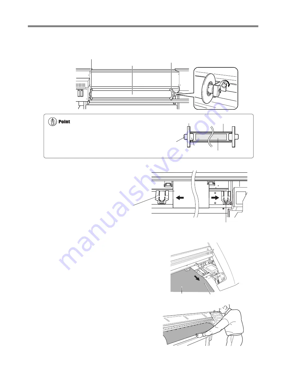
2-2 Loading Media

4

Fit the right-hand media flange all the way into the hole on the right-hand side of the roll media, and
tighten the retainer screw to secure in place.

5

Move the media clamps to the two ends of the platen.

6

Pass the end of the media from the back of the
machine to the front.

Pull out the media until the sensor is hidden

from view.

7

Grasp the center of the end of the media at the
front of the machine, and slowly pull the media
out straight to the position shown in the figure.

Media

Front

Sensor

Roll media

Media flange (left)

Media flange (right)

Media clamp

Media clamp

Reforcement pipe is included with SJ-740/640. When roll media sag severely,
use the reinforcement pipe inserted into the roll media. After use, remove the
reinforcement pipe from the paper tube.

Roll media

Media frange

2 in.

3 in.

Reinforcement pipe

Содержание SJ-540

Страница 1: ...fications of this product are subject to change without notice The operation manual and the product have been prepared and tested as much as possible If you find any misprint or error please inform us...

Страница 2: ...This Class A digital apparatus meets all requirements of the Canadian Interference Causing Equipment Regulations CLASSE A AVIS Cet appareil num rique de la classe A respecte toutes les exigences du R...

Страница 3: ...23 Step 4 Remove the Protective Media 25 1 4 Connecting the Cables 26 Connecting the Power Cord 26 Connecting to the Computer 27 1 5 Switching On the Power for the First Time 29 Step 1 Install Ink Car...

Страница 4: ...s for Printing 55 Feed Correction 55 Bidirectional Correction 56 3 7 Stopping Printing Operations 59 Stopping Printing Operations 59 Pausing Printing Operations 59 3 8 When Not in Use for a Prolonged...

Страница 5: ...84 The Machine Doesn t Run 84 Clean Attractive Printing Is Impossible 85 The Media Becomes Jammed 88 What to Do If the Printing Carriage Does Not Operate 89 6 2 What to Do If an Error Message Appears...

Страница 6: ...K Built in Print Server This machine has a built in print server Roland PrintServer as a network interface When you use the print server you can send printing data to the machine from anywhere on the...

Страница 7: ...r abnormal op eration resulting in injury Ground the unit with the ground wire Failure to do so may result in risk of electri cal shock in the even of a mechanical prob lem Do not use with any electri...

Страница 8: ...r fire Do not allow ink or cleaning liquid to come into contact with eyes or skin Do not drink or deliberately smell ink or cleaning liquid Doing so may be hazardous to your health If ink or cleaning...

Страница 9: ...cleaning is in progress The printing carriage may move and cause injury To Ensure Safe Use Use the joining screws to secure the unit to the stand Failure to do so may result in falling of the unit le...

Страница 10: ...injury Before switching on the power be sure to install the drain bottle Otherwise discharged fluid may leak from the machine When the reinforcement pipe is in serted into the paper tube do not angle...

Страница 11: ...messages To Ensure Safe Use Rating label Use a rated power supply Do not place hands within the space to the front of the unit while in operation Ink cartridge CAUTION Read all Warnings and Procedure...

Страница 12: ...le gauche signifie que le fil lectrique doit tre d branch de la prise propos des symboles Ne pas d monter r parer ou modifier Le non respect de cette consigne pourrait causer un incendie ou provoquer...

Страница 13: ...les yeux ou la peau Ne pas boire ou ni respirer d lib r ment l encre ou le liquide nettoyant Cela est dangereux pour la sant Si de l encre ou le liquide nettoyant viennent en contact avec les yeux rin...

Страница 14: ...ait causer des d fauts dans l appareil entra nant des blessures Utiliser les vis fournies pour bien fixer l appareil sur le support Le non respect de cette consigne pourrait causer des d fauts dans l...

Страница 15: ...essures Ne pas toucher le panneau de commande pendant le nettoyage des t tes ou d autres pi ces Le chariot d impression peut bouger et causer des blessures Ne pas oublier d installer le guide de m dia...

Страница 16: ...Ne pas d monter la cartouche Conserver hors de la port e des enfants Ne pas emmagasiner das temp ratures hautes ou basses La cartouche d encre CAUTION Read all Warnings and Procedures in the User s M...

Страница 17: ...15 1 Getting Started This section describes what to do when you first open the packing carton including installing the machine and connecting it to a com puter...

Страница 18: ...ashers 6 Hexagonal wrench 1 Pipe 1 Media flanges 2 Flange retaining pins 2 Drain bottle 1 Software RIP 1 User s manual 1 Replacement blade for separating knife 1 Roland PrintServer CD ROM 1 Transport...

Страница 19: ...Started POWER 1 2 Part Names Front View Front cover Sheet loading lever Cover Operation panel Cover Ink cartridge ports Drain bottle RJ 45 Ethernet connector Main power switch Rear View Power connecto...

Страница 20: ...e Inside the Front Cover Media clamp Display TEST PRINT key SETUP key CLEANING key SHEET CUT key MENU key ENTER key PAUSE key PAUSE LED BASE POINT key BASE POINT LED POWER key SETUP LED Operation Pane...

Страница 21: ...fire Unpacking and installation must be carried out by four or more persons Otherwise the machine or the stand may fall resulting in injury Install in a level and stable location Otherwise the unit m...

Страница 22: ...d legs with your hand attach the left and right hand casters 2 Set the stand upright so that the casters are at the bottom and place the machine on the stand The front and rear of the stand are as sho...

Страница 23: ...21 Chapter 1 Getting Started 1 3 Assembling and Installing 3 Use the included large bolts to secure the machine to the stand Three places each on the left and right Washer Bolt Large...

Страница 24: ...nd secure in place with the flange retaining pins Media guide Front Short Long Rear Bolts Small Right hand side of the back of the unit Left hand side of the back of the unit Flange retaining pins 2 M...

Страница 25: ...nsert the drain tube securely into the bottle stand Leave the drain bottle attached at all times removing it only when moving the machine or disposing of collected ink When you remove the stopper from...

Страница 26: ...ation about how to dispose of discharged ink 4 5 Disposing of Discharged Ink When the level of collected fluid is in this range detach the drain bottle and dispose of the discharged ink Drain bottle B...

Страница 27: ...ng the machine remove all protective media Front 2 Peel off the tape 4 Remove the retainer 1 6 Peel off the tape 5 Remove the retainer 2 3 Peel off the tape and remove the packing Pull straight back t...

Страница 28: ...the unit are switched off Arrange the power cord and interface connection cable to prevent tripping when moving around the unit Use only with a power supply of the same rating as indicated on the uni...

Страница 29: ...Connection to a Parallel Connector When making the connection to the computer using a printer cable connect the printer cable at the position shown in the figure Cables are available separately One w...

Страница 30: ...ring the Cable Pass the cable through the established location making sure that it does not touch the loaded media If the cable touches the media during printing media feed may be obstructed resulting...

Страница 31: ...ink cartridge is dropped the shock due to the fall may damage the ink cartridge and make it unusable When installing and removing an ink cartridge do not rush Detach the cartridge gently Sudden moveme...

Страница 32: ...ur cartridges firmly as far as they will go Cleaning starts The cartridges are inserted and removed while the operation is in progress Follow the messages on the display to carry out the procedure Cle...

Страница 33: ...31 2 Basic Operation This describes the sequence of basic operations from switching on the power to performing printing...

Страница 34: ...ver the platen If the machine is allow to stand to with the printing heads uncapped for a pro longed period the printing heads may become irreversibly clogged Before switching off the main power be su...

Страница 35: ...tching Off the Power at the End of the Day Press and hold down the POWER key for one second or longer to switch off the sub power The POWER LED goes out Leave the pinch rollers raised when not in use...

Страница 36: ...cause injury Load roll media at the proper position Otherwise the roll may fall resulting in injury When the reinforcement pipe is inserted into the paper tube do not angle the roll media The reinforc...

Страница 37: ...t the media until the sensor is hidden from view 7 Grasp the center of the end of the media at the front of the machine and slowly pull the media out straight to the position shown in the figure Media...

Страница 38: ...width W 1234 mm Top menu The SETUP LED lights up When the machine will remain unused for an extended period remove roll media from the machine and store it If roll media is left mounted on the machin...

Страница 39: ...with the guide line Rear View Remove the left hand media flange at the back of the unit Move the right hand media flange at the back of the unit to a position where it does not touch the loaded media...

Страница 40: ...ges When the lever is moved to position 1 low One beep When the lever is moved to position 2 middle Two beeps When the lever is moved to position 3 high Three beeps 5 Close the front cover The printin...

Страница 41: ...loose from the media clamps After about 1 m 3 ft of media has been fed check the positioning of the media clamps If the media looks like it may come loose from the media clamps adjust the positioning...

Страница 42: ...SETUP LED is lighted hold down the SETUP key for at least one second 3 Move the sheet loading lever toward the back of the unit The pinch rollers rise to release the media 4 Remove the media Dependin...

Страница 43: ...dia to rub against the heads which may result in a paper jam or damage to the heads The printing heads may be left uncapped that is the printing carriage may remain over the platen If the machine is a...

Страница 44: ...out a printing test The test pattern is printed 2 If dot drop out is present clean the heads For more information about head cleaning see 4 1 Cleaning the Printing Heads Downloading Printing Data Pri...

Страница 45: ...43 3 A Wide Variety of Operations This section describes a wide variety of operations and functions grouped by task...

Страница 46: ...hipping the machine Do not allow a removed ink cartridge to sit out for any length of time Doing so may result in clogging of the heads If ink runs out replace immediately with an ink cartridge design...

Страница 47: ...s switched on Operation is stopped or paused 1 Remove the ink cartridge from the ink cartridge port 2 Insert new ink cartridge Ink cartridge ports Be sure to use genuine SOL INK cartridges from Roland...

Страница 48: ...ection for EMPTY MODE under INK CONTROL is set to CONT or to STOP The default setting is STOP When Set to STOP Pause STOP causes operation to pause immediately when ink needs to be replaced Printing i...

Страница 49: ...ck the amount of remaining ink for ink car tridges 1 through 8 3 Continuing by pressing the key lets you check the amount of remaining ink for ink car tridges 9 through 12 Much Little Remaining ink In...

Страница 50: ...orward and backward movement and the scan direction the direction of movement of the printing carriage Next printing Margin setting on the computer Feed direction start location Scan direction start l...

Страница 51: ...e next printing operation starts here For roll media when the media has been returned toward the back of the unit with the key manually roll the media back onto the roll so that all of the media at th...

Страница 52: ...standby position when not printing problems such as drying out of the printing heads or dot drop out during printing may occur For this reason about 60 seconds after pressing the key to move the prin...

Страница 53: ...s for the margins refer to the documentation for the RIP you re using Next Printing Margin Setting made using the software RIP First Printing Printing area for the next printing operation When a media...

Страница 54: ...to move the printing carriage the printing carriage returns to the standby position Also the printing carriage returns to the standby position when about 30 seconds passes during this interval after...

Страница 55: ...the key to make the following screen appear on the display When you do this the printing carriage moves to the left edge of the printing area 7 Use the and keys to move the marker at the right edge of...

Страница 56: ...ey 4 Specify a printing area for the left right direc tion the direction of printing carriage move ment that matches the width of the media For more information see 3 4 Setting the Margins Setting the...

Страница 57: ...se the and keys to set the value you then press the ENTER key Perform correction to ensure uniform dot spac ing If there are gaps in the test pattern reduce the value If there are overlapping areas in...

Страница 58: ...ess the key to make the following screen appear on the display 3 Press the ENTER key to start printing a test pattern After the printing test has finished the media is fed to a position that lets you...

Страница 59: ...eys to set the value you checked in step 4 then press the ENTER key In case of SETTING NO 1 enter H1 71 2 H2 8 H3 7 H4 8 H5 6 and H6 7 9 Use the and keys to Choose Setting No 2 SETTING NO 2 appears In...

Страница 60: ...TING 8 then press the ENTER key The adjustment values are saved in the memory number you selected Loading an Adjustment Value 1 Press the MENU key and press the key to make the following screen appear...

Страница 61: ...ion of printing instructions from the computer 3 Hold down the SETUP key for one second or longer Any remaining data is cleared Pausing Printing Operations Press the PAUSE key The PAUSE LED lights up...

Страница 62: ...eriod 1 When the machine is out of use for about a month a warning beep sounds and the follow ing message appears on the display 2 Press the POWER key to switch on the sub power Cleaning is performed...

Страница 63: ...61 4 Maintenance This section describes how to clean the printing heads daily care and maintenance and the like...

Страница 64: ...EANING key and press the key to select the printing head group to clean Press the ENTER key to start head cleaning Also holding down the CLEANING key for at least one second starts head cleaning for a...

Страница 65: ...Not Correct the Drop out Problem If performing cleaning several times at the POWERFUL menu does not correct the image drop out problem use the included cleaning kit For information on how to use the...

Страница 66: ...R key 3 Press the and keys to select CLEAN ING 4 Press the ENTER key The screen shown in the figure appears and the printing carriage moves to the middle of the left cover 5 Make sure the screen shown...

Страница 67: ...the rubber caps and the area around them Use a cleaning stick to wipe off any buildup of dust or grime from the rubber caps If there is dust on the sponges wipe it off with the cleaning stick Stainle...

Страница 68: ...he POWER key to switch on the sub power 14 Load media and carry out a printing test Examine the results of the printing test and make sure that all dots are printed attractively If necessary perform h...

Страница 69: ...it off the hook 4 Remove the wiper 5 Install the new wiper Use the tweezers to press the area shown in the figure and engage the wiper on the hook 6 Follow steps 11 through 13 in 4 2 Cleaning Using t...

Страница 70: ...eaning the Pinch Rollers Moisten a cloth with neutral detergent diluted with water wring dry and wipe gently Cleaning the Reflective Tape If the tape becomes dirty moisten a cloth with neutral deterge...

Страница 71: ...r dance with regional laws and regulations The POWER LED goes out Drain bottle When the discharged ink is within this range dispose of it If discharged ink is allowed to exceed this range it may spill...

Страница 72: ...nting carriage is pulled out automatically through menu operation If the machine is allowed to stand for a prolonged period with the printing carriage pulled out head clogging or even damage to the pr...

Страница 73: ...key to display the screen shown in the figure Be sure to discard the discharged ink Attempting to clean the heads while discharged ink remains may cause discharged ink to overflow from the bottle For...

Страница 74: ...rform cleaning for the re maining four colors 8 When head cleaning finishes the sub power shuts of automatically Switch off the main power switch 9 Detach the power cord and the cable connect ing the...

Страница 75: ...73 5 Menus and Keys This section contains a flowchart of the menus and describes the control panel keys and the menu items...

Страница 76: ...menu screen or move down one level Select an item Select the value for a setting Executes the menu Locks in the value for a setting W 1234 mm Load the media and press the SETUP key Printable width of...

Страница 77: ...ER key to perform head cleaning of B Group CLEANING B GROUP Press the ENTER key to perform head cleaning of C Group CLEANING C GROUP CLEANING ALL Press the CLEANING key to perform all head cleaning Pr...

Страница 78: ...EDGE CANCEL HIGH MIDDLE LOW 30 to 10 In steps of 1 2 H1 H2 H3 0 0 0 H4 H5 H6 0 0 0 ADJUST BI DIR SETTING NO 1 ADJUST BI DIR TEST PRINT MENU ADJUST BI DIR CALIBRATION SETTING CALIBRATION TEST PRINT ME...

Страница 79: ...CLEANING HEAD CLEANING ALL MEDIUM HEAD CLEANING A MEDIUM HEAD CLEANING C MEDIUM HEAD CLEANING B MEDIUM HEAD CLEANING ALL POWERFUL HEAD CLEANING A POWERFUL HEAD CLEANING C POWERFUL HEAD CLEANING B POW...

Страница 80: ...the setting display this menu then move the lever on the side of the unit s printing carriage For more information see 2 2 Loading Media When Loading Thick Media If print shows a problem clean the pr...

Страница 81: ...ASH This washes the printing heads with optionally available cleaning cartridges For more information see 4 7 When Moving the Unit This adjusts for slippage when performing bidirectional printing This...

Страница 82: ...menu settings to their original values when shipped from the factory For more about the factory defaults for the various settings see the Default value entry for each menu setting in this section This...

Страница 83: ...e paused causes remaining data to be cleared and cancels the media s setup state This sets the print start location in the scan direction the direction of printing carriage movement For more infor mat...

Страница 84: ...ted from the roll You cannot sever a piece of me dia while printing is in progress This enters the menu mode When a menu is displayed the and keys move to the next menu the moves to a submenu and the...

Страница 85: ...83 6 What to Do If This section describes error messages that may appear on the dis play and how to resolve problems that can occur during operation...

Страница 86: ...displayed printing doesn t start even when data is sent from the computer Is the PAUSE LED illuminated If the PAUSE key has been pressed and the PAUSE LED is lighted the unit has been paused To resum...

Страница 87: ...the printing head has been adjusted it is necessary to perform bidirectional correction For more information about bidirectional correction see 3 6 Making Corrections for Printing Bidirectional Correc...

Страница 88: ...before you start printing perform a printing test to make sure there is no dot drop out Printing goes beyond the loaded media Is the reflective tape dirty If the reflective tape becomes soiled the wid...

Страница 89: ...cts the media flange or the like at the back of the unit shift the retainer to a location where the media doesn t make contact If the media touches an obstruction while printing is in progress normal...

Страница 90: ...to turn on the sub power 4 Correct whatever caused the media to jam For example if thick media has been loaded then adjust the height of the printing heads 5 Load the media and carry out setup 6 Press...

Страница 91: ...become clogged or even damaged Capping the Printing Heads 1 Make sure the main power is switched off then open the cover on the right side of the machine 2 Open the front cover and move the printing c...

Страница 92: ...to Do If 5 When the printing carriage comes into contact with the caps rotate the pipe one or two turns more Make sure the printing carriage and the caps are touching then contact your authorized Rola...

Страница 93: ...or front cover Load the media and try again Press the ENTER key to continue Replace the empty ink cartridge Insert the specified ink cartridge Take out the specified ink cartridge Insert the specifie...

Страница 94: ...Do not leave the unit with the printing carriage not in standby position Recovery from this problem is impossible Use the POWER key to switch the power off First raise the temperature of the area wher...

Страница 95: ...93 7 Appendix...

Страница 96: ...or usable media Ink cartridges Type Capacity Colors Printing resolution Printing dot resolution Distance accuracy Printing heads cleaning Interface Power saving function Power consumption Printing mod...

Страница 97: ...Impedance Connector type Values 100 m S UTP Type category 5 100 Ohm RJ 45 Standard Input signals Output signals Level of input output signals Transmission method Bidirectional parallel interface comp...

Страница 98: ...1 16 in Surface to be printed must face outward C Core inner diameter for roll media 50 8 mm or 76 2 mm 2 in or 3 in D Maximum weight for roll media 20 kg 44 1 lb E Roll media that is not taped down t...

Страница 99: ...and the printing area appears on the display The printing area is normally 10 mm 3 8 in inward from the respective left and right hand edges of the media When the printable width have been specified w...

Страница 100: ...ng Continuous Printing The media cutoff location that is used when a media cutoff command is sent from the computer is determined as follows Start of the next printing operation End of printing Locati...

Страница 101: ......

Страница 102: ...R5 030905...

Отзывы: