background image

Moving a Saved Symbol to a New

Computer

For instructions on how to save symbols, check the CutStudio Help.

Procedure

Copy the Symbol folder from the path below.

Store the folder in a desired location or move it.

C:¥ProgramData¥Roland DG Corporation¥CutStudio

¥Symbol


If the Folder Is Not Displayed

In "Sample Data Cannot Be Found," configure the settings for 

displaying

hidden folders

.


Copy the Symbol folder to a new computer.

Copy the folder to the same location on the new computer. 

If the folder is not displayed on the new computer, adjust the settings to

display hidden folders.


Содержание GR-420

Страница 1: ...to use the machine Basic Edition If you have already mastered the basic operation use this manual for an introduction to more advanced operations Application Edition Windows version Macintosh version...

Страница 2: ...e GR 640 540 420 Simple Basic Cutting Improving the Finish Maintenance Replacement Troubleshooting Error Message List Menu Flow Chart Specifications Simple Basic Cutting Maintenance Replacement Troubl...

Страница 3: ...luded software to create various products The Windows version of the application edition provides procedures that use a computer on which Windows is installed User s Manual Application Edition Macinto...

Страница 4: ...no liability for any loss or damage of data resulting from computer malfunction or damage Always back up important data Support Support information made available via the Roland DG Corp website is upd...

Страница 5: ...What Is the GR 640 GR 540 GR 420 What the GR 640 GR 540 GR 420 Can Be Used For Loadable Materials Cuttable Area Part Names Carriage LED Lamp...

Страница 6: ...utting Preparations for Printing and Cutting When Using CutStudio Preparations for Printing and Cutting When Using Illustrator Preparations for Printing and Cutting When Using CorelDRAW Cutting Perfor...

Страница 7: ...al 200 mm or more GR 540 156 to 1 548 mm 6 to 60 inches GR 420 156 to 1 224 mm 6 to 48 inches Never load media that weighs over 40 kg 88 19 lb The machine may fail to withstand the weight causing the...

Страница 8: ...EXTEND Explanation of Cutting Area The cutting area along the material s horizontal plane the direction in which the cutting carriage moves is determined by the position of the pinch rollers The cutt...

Страница 9: ...For the range for assured accuracy refer to the specifications Cutting area Pinch roller Using Various Types of Materials...

Страница 10: ...nel Use the display and the keys to operate and set this machine 5 Cutting carriage Install the blade holder This part moves to the left and right to cut the material 6 Power switch Turns the machine...

Страница 11: ...llers are lowered this key lights PINCH 17 Display This displays various setting menus and other information 18 Cursor keys You use these to select settings for menu items to move the material and for...

Страница 12: ...s each time that you press this key The display switches in the following order currently set cutting conditions menu mode width display screen MENU 25 MEMORY key Use this key to apply recorded cuttin...

Страница 13: ...Carriage LED Lamp Normal The blue lamp is steadily lit or flashes Error The red lamp flashes and an error message is displayed Refer to Error Message List and clear the error...

Страница 14: ...low the procedure you can create a sticker like the one shown in the figure below Items Required Other Than the Machine A computer with CutStudio installed Roll material CutStudio Be sure to install t...

Страница 15: ...rial Installing the Cutting Tool Performing a Cutting Test Setting the Origin Creating Cutting Data 1 Creating Cutting Data 2 Entering Characters and Shapes Saving Cutting Data Performing Cutting Remo...

Страница 16: ...d media that weighs over 40 kg 88 19 lb The machine may fail to withstand the weight causing the machine to tip over or the material to fall If using flat material or similar material refer to Using V...

Страница 17: ...erial between the pinch rollers and the grit rollers Exercise caution to prevent the material from touching the shaft of the pinch rollers The shaft is coated in grease so grease may be transferred fr...

Страница 18: ...ial cannot be fed correctly Place the right edge of the roll material over the grit roller on the right edge 1 Grit roller 2 Right edge of the roll material Slide the roll material to place its left e...

Страница 19: ...in two locations one on the top and one on the bottom Ruler gradation Place the left and right pinch rollers over the grit rollers on both edges of the roll material and the middle pinch rollers over...

Страница 20: ...arriage moves to the origin and the width of the roll material is shown on the display Handling Error Messages If the following error message appears on the display one of the pinch rollers is not in...

Страница 21: ...s in the correct positions Place them so that each is positioned over a grit roller Position the pinch rollers on the edges so that each one is 25 mm or more inside of the respective left or right edg...

Страница 22: ...the worst case this problem may cause an error or malfunction or damage to the material Materials That Require Feeding Roll material and long flat material that is longer than 1 6 m 63 in If the Mate...

Страница 23: ...ress ENTER The set length of the material moves out to the front then is immediately pulled back and taken up again Press the MENU key to return to the screen shown in the figure If the Material Comes...

Страница 24: ...sheet Use the optimal blade for cutting to sheet material Items Required Included Items Blade holder pin Blade Adjusting the Amount of Blade Extension Adjust the amount of blade extension according t...

Страница 25: ...carriage screw Install the cutting tool in the cutting carriage Normally install it in the position shown in the figure in the rear Install it in the front position when cutting perforated lines Tight...

Страница 26: ...thin carrier paper If you are not able to obtain stable cutting results changing the amount of blade extension can yield better results For more information refer to the pages indicated below General...

Страница 27: ...k the cutting quality for the material before you perform the actual cutting Procedure Setting the Number of Cutting Tests to Perform Check that the PEN FORCE slider is at the center position at 0 on...

Страница 28: ...tatus of the finished product Press ENTER to select the setting You are returned to the following screen in this example three cutting tests will be performed Press ENTER The test pattern is cut The p...

Страница 29: ...finishes the material is automatically fed to the front Peel off circle 1 Use the tweezers or a similar tool to peel off the cut shape and then check the cutting quality Circle 1 Tweezers If Circle 1...

Страница 30: ...Paper Changing the Blade Force Peel off rectangle 2 Use the tweezers or a similar tool to peel off the cut shape and then check the cutting quality Rectangle 2 If the Blade Leaves Faint Traces on the...

Страница 31: ...If the Traces Left by the Blade Are Indistinct Too Deep Changing the Blade Force Setting the Origin...

Страница 32: ...to display the following screen Moving the Cutting Carriage at High Speed Press and to move the cutting carriage to the location you want to set as the origin Press to move the material backward and...

Страница 33: ...Hold down ORIGIN for one second or longer The screen flashes This completes all preparations for cutting Creating Cutting Data 1...

Страница 34: ...installed click here If you are using a Macintosh click here Procedure Start CutStudio Windows 10 and Windows 7 On the Start menu click All Programs or Programs click Roland CutStudio and then click...

Страница 35: ...2 Set the Model Procedure From the File menu click Cutting Setup The Cut Setting window appears...

Страница 36: ...Use Name under Printer to select the model name of the cutting machine to use Creating Cutting Data 2...

Страница 37: ...Creating Cutting Data 2 Set Material Size Procedure Click Change under Media Size Click Get from Machine The cuttable area is displayed...

Страница 38: ...If a Message Saying The machine is not responding Is Displayed Refer to The Machine Doesn t Run and check the machine and computer settings Click OK Click OK in the Cut Setting window...

Страница 39: ...The cutting area is set The white area is the cutting area Characters and shapes outside this area will not be cut 1 Cutting area...

Страница 40: ...2 The origin set in Setting the Origin the cutting start position corresponds to the lower left corner of the screen in CutStudio Entering Characters and Shapes...

Страница 41: ...Shapes Enter Characters and Shapes This example explains the procedure for entering the word SALE and creating a frame to make it easy to peel off afterward Procedure Click Click anywhere in the white...

Страница 42: ...d then change the size of the characters and appear around the characters Drag the and symbols around the text box to change the size of the characters Select the object and then click in the menu bar...

Страница 43: ...configure advanced settings in the Properties palette From the Object menu click Weed The Weed dialog box appears Select the Weed Border check box and then click OK...

Страница 44: ...For details on waste removal lines see the CutStudio help Click and then move the characters with the waste removal frame added Move the object to the bottom of the screen close to the origin Select t...

Страница 45: ...t feeding more of the material than needed The leading edge of the loaded material is the bottom edge of the cutting area in the CutStudio screen Therefore positioning characters at the bottom of the...

Страница 46: ...following figure is displayed Select a folder where you want to save the data Enter a file name and then click Save The data you have created is saved Important The cutting area is not saved The cutt...

Страница 47: ...loaded the cutting area must be set again from the Cut Setting menu Performing Cutting...

Страница 48: ...cutting carriage moves at high speed Coming into contact with the moving carriage may cause injury Once the data has been prepared you are ready to start cutting If you are using a Macintosh click he...

Страница 49: ...ge the cutting conditions click Change clear the Use cutting conditions of machine check box and then enter the values This completes the cutting procedure for the characters SALE and the rectangle Re...

Страница 50: ...To Cancel Cutting Procedure Press PAUSE Hold down ENTER for one second or longer The data is canceled Removing the Material...

Страница 51: ...all Plug in for Illustrator before proceeding Installing Plug in for Illustrator Procedure Start Illustrator In Illustrator click Extensions Roland CutStudio from the Window menu The Roland CutStudio...

Страница 52: ...nt size to be the same as the cutting width displayed on the machine Set a length that is longer than the product that you want to create Enter SALE After you enter the text change the size of the cha...

Страница 53: ...ower left corner of the document It is better to position characters and shapes starting from the bottom of the document This makes it possible to prevent feeding more of the material than needed Illu...

Страница 54: ...Select the Auto Update check box in the palette With SALE selected click An outline is created...

Страница 55: ...Use Illustrator s rectangle tool to draw a frame around SALE Save the data Performing Cutting...

Страница 56: ...u are ready to start cutting Changing and Checking the Cut Settings Procedure On the palette select Output All Lines and then click Update Check that all the contour lines that you wish to cut are sho...

Страница 57: ...igure is displayed Select the model name of the machine on hand and then click Cut Cutting starts If the model name is not displayed see The Machine Doesn t Run When cutting is finished click Exit to...

Страница 58: ...er Procedure Click on the palette and then click Preferences Select the Use cut settings check box and then click OK Click on the palette and then click Cut Settings Cutting Setup will not be displaye...

Страница 59: ...When You Do Not Select the Use Machine Settings Check Box Cutting is performed with the settings shown in the following figure the Cut Setup screen When You Select the Use Machine Settings Check Box...

Страница 60: ...Cutting is performed with the machine settings Click OK To Cancel Cutting Procedure Press PAUSE Hold down ENTER for one second or longer The data is canceled...

Страница 61: ...Removing the Material...

Страница 62: ...ting has finished remove the material Procedure Press MENU several times to display the screen shown below Press ENTER The cutting carriage returns to the home position Press PINCH The pinch rollers r...

Страница 63: ...d to feed the material to the location that you want to cut The material is cut off at the position shown in the figure Groove along which the separating knife passes Hold down SHEET CUT for one secon...

Страница 64: ...After the material is cut the cutting carriage returns to the new origin...

Страница 65: ...ging the Cutting Speed Adjusting the Cutting in Amount Cutting Conditions General Guide Regarding Cutting Conditions Using a Variety of Materials Using Various Types of Materials Loading Flat Material...

Страница 66: ...the cutting test was that two shapes peeled off together change the blade force Procedure Check that the PEN FORCE slider is at the center position at 0 on the scale Press CUT CONFIG to display the f...

Страница 67: ...een Fine tuning the Blade Force After you set the blade force using the FORCE menu you can further fine tune the blade force using the PEN FORCE slider Use this operation when you want to make the bla...

Страница 68: ...This value is intended only as a rough guide The accuracy of this value is not guaranteed Improving the Finish...

Страница 69: ...eed When the cutting speed is fast and the material moves up and down during cutting an excessive load will be applied to the material In this situation as well reduce the cutting speed Procedure Pres...

Страница 70: ...Press ENTER to select the setting Press MENU to return to the original screen Improving the Finish...

Страница 71: ...adjust the amount of blade extension An adjustment of 0 5 millimeters can be made by rotating the cap one full turn General Guide for Amount of Blade Extension Use the following formula as a rough gu...

Страница 72: ...Improving the Finish...

Страница 73: ...e offset mm Pinching force ZEC U5032 General signage vinyl 30 to 100 30 or less 0 25 2 to 6 General inkjet vinyl 50 to 100 3 to 6 Iron on print vinyl 50 to 100 2 to 6 ZEC U5025 General signage vinyl 4...

Страница 74: ...If the desired cutting results are not obtained for example if uncut areas remain even after the blade is replaced refer to Uncut Areas Remain or Cut Edges Are Not Clean Improving the Finish...

Страница 75: ...erial Using Flat Material If flat material is used it must be at least 60 mm longer than the vertical size of the cutting data This is the length required for the pinch rollers to feed out the materia...

Страница 76: ...s for Sprocket Feed Sprocket fed material has perforations along each edge If the pinch rollers are positioned over the perforations the material cannot be fed correctly Load the material as shown in...

Страница 77: ...and load the material Procedure If the pinch rollers have lowered press PINCH Check that the pinch rollers have risen Place the right edge of the material over the grit roller on the right edge For A...

Страница 78: ...traighten the material Align the right edge of the material so that it is parallel to the gradations of the rulers in two locations one on the top and one on the bottom Ruler gradation Place the left...

Страница 79: ...Select PIECE for the material type Using Various Types of Materials Press ENTER The pinch rolls lower and the carriage and material move When the movement is finished the cuttable width and length ar...

Страница 80: ...Improving the Finish...

Страница 81: ...the material see Loading Roll Material or Loading Flat Material 2 The position of the left pinch roller for material having widths of 156 mm and 306 mm 3 The position of the left pinch roller for mate...

Страница 82: ...1 Grit pattern 2 Pinch roller Improving the Finish...

Страница 83: ...the material with minimal waste by setting the origin to an uncut position on the material Procedure Load the material in the machine and make it ready for cutting setup condition Press and to move t...

Страница 84: ...one second or longer ORIGIN SET flashes on the display When the setting is complete the following screen appears Send the cutting data from the computer Cutting is performed using the specified origin...

Страница 85: ...Maintenance Replacement Cleaning Cleaning Replacing the Blade and the Separating Knife Replacing the Blade and the Separating Knife Consumable Items Consumable Items...

Страница 86: ...ecified by the instructions and never touch any area not specified in the instructions Sudden movement of the machine may cause injury or burns Never use a solvent such as gasoline alcohol or thinner...

Страница 87: ...using a brush Never use a metal brush Cleaning the Blade Holder Cap If there is a buildup of pieces of material or dust inside the cap loosen the cap remove it and then remove any foreign matter If pi...

Страница 88: ...to perform operations as specified by the instructions and never touch any area not specified in the instructions Sudden movement of the machine may cause injury or burns Remove the material before pe...

Страница 89: ...CAUTION Never touch the tip of the blade Doing so may result in injury Remove the old blade...

Страница 90: ...1 Press this pin 2 Old blade Install a new blade 1 New blade 2 Cutting tool with the new blade installed Install the cutting tool Installing the Cutting Tool Replacing the Separating Knife...

Страница 91: ...pull it out in the direction of the arrow When doing this do not pull it back toward you Install a new knife The knife is secured in place by the magnet 1 Magnet 2 Positioning groove Slowly insert the...

Страница 92: ......

Страница 93: ...of the blade is broken Uncut areas remain even though the blade force has been increased by 50 to 60 gf Cuts are not as clean as they used to be The material starts to curl up from the carrier paper w...

Страница 94: ...t cleanly because the tip of the blade will not turn smoothly If corners or curved sections are not cut cleanly or cuts start looking like perforated lines or if similar problems occur refer to Cleani...

Страница 95: ...rkness of an Aligned Image Illustrator Data Cannot Be Imported Sample Data Cannot Be Found The Material Slips Away from the Pinch Rollers during Cutting The Material Slips Away from the Pinch Rollers...

Страница 96: ...alling the Driver Windows 8 1 Uninstalling the Driver Windows 7 Connecting Two or More Instances of This Machine to a Single Computer Connecting Multiple Units with a USB Cable The Driver Is Displayed...

Страница 97: ...t Select the loaded material press the ENTER key and then set the machine so it is ready to receive cutting data Are the software application settings incorrect Select the appropriate driver for the m...

Страница 98: ...al Cannot Be Set Up Using PIECE Length Is Not Displayed Is the material 1 6 m or longer If flat material 1 6 m or longer is set up using PIECE the machine recognizes it as a roll Using Various Types o...

Страница 99: ...of an Aligned Image It is possible to change the darkness of an image imported into CutStudio Procedure From the File menu click Preferences On the General tab enter a value in the Image Darkness box...

Страница 100: ...Click OK...

Страница 101: ...n Illustrator 8 0 or EPS 8 0 format Illustrator 8 0 and EPS 8 0 are the Illustrator file formats that can be imported into CutStudio If using a higher version save files as a lower version before impo...

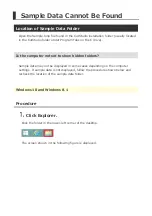
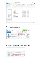
Страница 102: ...the computer not set to show hidden folders Sample data may not be displayed in some cases depending on the computer settings If sample data is not displayed follow the procedure shown below and reche...

Страница 103: ...Click the View tab Select the Hidden items check box...

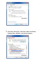
Страница 104: ...Windows 7 Procedure From the Start menu click Computer In the Organize menu click Folder and search options The screen shown in the following figure is displayed...

Страница 105: ...Click the View tab and then select the Show hidden files folders and drives option...

Страница 106: ...Click OK...

Страница 107: ...e contact with the inner surfaces of the machine during cutting Such contact not only damages the material but also hinders normal material feed and causes the material to slip out of position Was the...

Страница 108: ...marks cannot be detected if decorations or colors are on the material Crop marks also may not be detected on glossy material even if it is white Materials That Can Be Used for Printing and Cutting Doe...

Страница 109: ...deg Be sure to set the ROTATE menu to 0deg when using crop marks Crop marks cannot be read if this is set to 90deg Setting the Direction of the Coordinate Axis for Cutting ROTATE Is the machine expose...

Страница 110: ...cified by the software match those specified on the machine Manual mode On the machine correctly set the distance specified by the software Are the crop marks at the correct positions If the angle for...

Страница 111: ...uality QUALITY When using roll material was the amount of material to be cut pulled out before performing cutting If cutting is performed without pulling out the material the material may slip or a mo...

Страница 112: ...If it is replace the blade with a new one Consumable Items Blade Is there any buildup of dust or material adhesive on the tip of the blade Remove and clean the blade Is there any buildup of pieces of...

Страница 113: ...d or have horns Setting the Amount of Offset for the Tip of the Blade OFFSET Are the blade force and cutting speed appropriate Carry out cutting tests and adjust the settings until cutting can be perf...

Страница 114: ...or deformed If the blade protector is damaged the material may not be cut correctly even if the machine s settings and the installation of the blade and blade holder are all correct If this happens c...

Страница 115: ...tip adjustment and blade force appropriate for the material being cut Perform a cutting test and adjust the blade tip and blade force appropriately Performing a Cutting Test General Guide Regarding Cu...

Страница 116: ...than 0 on the Cut screen the number is added to the number of cuts Is the machine s OVERLAP setting a number from 1 to 10 Set the machine s OVERLAP setting to OFF Cutting in the Same Position Repetit...

Страница 117: ...nnect the machine to the computer with the USB cable and turn on the machine If a message saying Found new hardware appears click Close Disconnect the USB cable from every printer except the machine O...

Страница 118: ...m Click the name to select it From the Action menu click Uninstall On the Confirm Device Uninstall window click OK Close Device Manager Disconnect the USB cable from the computer and then restart Wind...

Страница 119: ...http startup rolanddg com...

Страница 120: ...edure shown below Procedure Connect the machine to the computer with the USB cable and turn on the machine If a message saying Found new hardware appears click Close Disconnect the USB cable from ever...

Страница 121: ...and then double click it The name of your machine or Unknown device appears below the selected item Click the name to select it From the Action menu click Uninstall On the Confirm Device Uninstall wi...

Страница 122: ...Follow the procedure in Installing the Driver for Windows and reinstall the driver from the beginning http startup rolanddg com...

Страница 123: ...ter with the USB cable and turn on the machine If a message saying Found new hardware appears click Close Disconnect the USB cable from every printer except the machine Click the Start menu and then r...

Страница 124: ...this device check box and then click OK Close Device Manager The name of your machine or Unknown device appears below the selected item Click the name to select it Disconnect the USB cable from the co...

Страница 125: ...ect the connector cable between the computer and the machine Log on to Windows as the computer s administrator Right click the Start menu click Control Panel and then click Uninstall a program Select...

Страница 126: ...ick Yes The setup program for the driver starts Click Uninstall Select the machine you want to delete and then click Start If a window prompting you to restart the computer appears click Yes The unins...

Страница 127: ...Installation Procedure...

Страница 128: ...d then disconnect the connector cable between the computer and the machine Start Windows Click Desktop Move the mouse pointer to the lower right corner of the screen to display the Charms bar and then...

Страница 129: ...er and then open the drive and folder containing the driver Double click SETUP64 EXE 64 bit version or SETUP EXE 32 bit version If a User Account Control window appears click Allow The setup program f...

Страница 130: ...ck View devices and printers If you can see the icon of the machine to delete right click it and then click Remove device Download the driver for the machine you want to delete from the Roland DG Corp...

Страница 131: ...r cable between the computer and the machine Log on to Windows as the computer s administrator From the Start menu click Control Panel and then click Uninstall a program Select the driver of the machi...

Страница 132: ...low The setup program for the driver starts Click Uninstall Select the machine you want to delete and then click Start If a window prompting you to restart the computer appears click Yes The uninstall...

Страница 133: ...Installation Procedure...

Страница 134: ...hine so that the computer can distinguish between output destinations The machine s default setting is A When connecting two or more machines the second machine and every machine thereafter must be co...

Страница 135: ...ne While holding down PINCH switch on the power switch The screen shown in the following figure is displayed Press and to select a setting other than A It is possible to select a value from B to E In...

Страница 136: ...set in step 3 is displayed 2 Connect and Change the Computer s Printer Settings Procedure Connect the machine to the computer using the USB cable The driver is installed Open Devices and Printers Rola...

Страница 137: ...nters Windows 8 1 From the Start screen click Apps and then click Control Panel Click Hardware and Sound and then click Devices and Printers Windows 7 From the Start menu select Devices and Printers R...

Страница 138: ...as Been Installed Procedure Start CutStudio From the File menu click Cutting Setup Click the Printer Name Check that GS 640 B is displayed If the screen looks similar to the one displayed in the figur...

Страница 139: ......

Страница 140: ...ectly it may be displayed as Unspecified in some cases Try the installation method described at the link below The Driver is Displayed as Unspecified URLs contained in this manual are subject to chang...

Страница 141: ...ed location or move it C ProgramData Roland DG Corporation CutStudio Symbol If the Folder Is Not Displayed In Sample Data Cannot Be Found configure the settings for displaying hidden folders Copy the...

Страница 142: ...Illustrator Installation Procedure Install from the following link http startup rolanddg com Supported Versions For information regarding the latest supported versions visit the Roland DG Corp website...

Страница 143: ...CorelDRAW Installation Procedure Install from the following link http startup rolanddg com Supported Versions For information regarding the latest supported versions visit the Roland DG Corp website...

Страница 144: ...terial Crop mark 2 or 3 is slanted by 5 degrees or more Press any key to clear the error message Reload the material Crop mark 3 is offset by 20 mm or more in the material movement direction Press any...

Страница 145: ...direct sunlight or intense indoor lighting Then turn on the power The machine is exposed to direct sunlight or strong indoor lighting and was not able to detect the origin immediately after the power...

Страница 146: ...Installing the Cutting Tool...

Страница 147: ...Menu Flow Chart...

Страница 148: ......

Страница 149: ......

Страница 150: ...20 to 600 gf Mechanical resolution 0 005 mm step Software resolution 0 025 mm step Distance accuracy 1 Error of less than 0 2 of distance traveled or 0 1 mm whichever is greater Repetition accuracy 1...

Страница 151: ...e setup guide setup guide 1 According to material and cutting conditions as specified by Roland DG Corporation 2 Excluding expansion contraction of the material 3 Range for assured repetition accuracy...

Страница 152: ...Cutting Cutting Perforated Lines Tiled Output Other Things That You Can Do Troubleshooting Sending Data from Illustrator CorelDRAW Printing and Cutting Cutting Perforated Lines Tiled Output Other Thin...

Страница 153: ...is necessary to install a plug in When Using Illustrator Required Items CutStudio Plug in for Illustrator Installing Plug in for Illustrator Install CutStudio and Plug in for Illustrator on the compu...

Страница 154: ...lug in for CorelDRAW Installing Plug in for CorelDRAW Install CutStudio and Plug in for CorelDRAW on the computer on which CorelDRAW is installed Sending Data from CorelDRAW Outputting Data Created in...

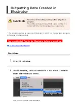
Страница 155: ...15 but the operation procedure is the same for other versions You must install Plug in for Illustrator before proceeding Installing Plug in for Illustrator Procedure Start Illustrator In Illustrator c...

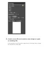
Страница 156: ...Create a new file and create a new design or open an existing file In this example you will create the design shown in the figure below Change the characters to outline data...

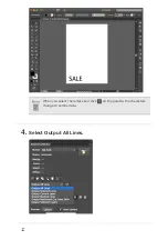
Страница 157: ...When you select characters and click on the palette the characters change to outline data Select Output All Lines...

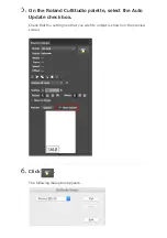
Страница 158: ...On the Roland CutStudio palette select the Auto Update check box Check that the cutting line that you wish to output is shown on the preview screen...

Страница 159: ...io The output data is always aligned at the origin of CutStudio regardless of the position in Illustrator This does not apply to data with crop marks Perform cutting Performing Cutting When perform cu...

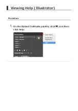
Страница 160: ...Viewing Help Illustrator Procedure On the Roland CutStudio palette click and then click Help...

Страница 161: ...Outputting Data Created in CorelDRAW You must install Plug in for CorelDRAW before proceeding Procedure Start CorelDRAW On the toolbar click The Roland CutStudio palette appears...

Страница 162: ...Create a new document and create a new design or open an existing file In this example you will create the design shown in the figure below Convert the characters to curved lines...

Страница 163: ...characters and click on the palette the characters change to outline data Select Output All Lines Select the Auto Update check box Check that the cutting line that you wish to output is shown on the...

Страница 164: ...Click CutStudio starts and the cutting line data is sent to CutStudio The output data is always aligned at the origin of CutStudio regardless of the position in CorelDRAW...

Страница 165: ...ut to CutStudio Character strings are not output to CutStudio Convert character strings to curved lines prior to outputting the data Line width fill and arrows are ignored Lines without width are not...

Страница 166: ...Viewing Help CorelDRAW Procedure On the Roland CutStudio palette click and then click Help...

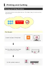
Страница 167: ...picture can be printed and cut This makes it easy to create your own original stickers Flow Diagram Create the data in CutStudio You can also use Illustrator CorelDRAW Print the data with the printer...

Страница 168: ...rations for Printing and Cutting When Using Illustrator Printing and Cutting Procedure Illustrator Printing and Cutting with CorelDRAW Preparations for Printing and Cutting When Using CorelDRAW Printi...

Страница 169: ...printer Fine paper coated paper art paper and PET Polyethylene Terephthalate Inkjet printerVinyl chloride material fine paper and coated paper Color White Automatic detection may not be possible for...

Страница 170: ...comfortable with the printing and cutting procedure by using the sample data first In this procedure you will create the sticker shown below Printing and Cutting Procedure CutStudio Items Required Oth...

Страница 171: ...o perform printing and cutting operations http startup rolanddg com Materials That Can Be Used for Printing and Cutting This example uses A4 size material Materials That Can Be Used for Printing and C...

Страница 172: ...cedure Step 1 Set the Printing and Cutting Areas Step 2 Import the Sample Data Step 3 Draw the Cutting Lines Step 4 Perform Printing Step 5 Load the Printed Material Step 6 Set the Alignment Method Se...

Страница 173: ...s 10 and Windows 7 On the Start menu click All Programs or Programs click Roland CutStudio and then click CutStudio Windows 8 1 At the lower left of the Start screen click to display the Apps screen C...

Страница 174: ...Use Name under Printer to select the model name of the machine on hand Click OK From the File menu click Print Cut...

Страница 175: ...the screen The printing area is displayed with dotted lines This area corresponds to the paper size specified in Set up the printer excluding the margins specified in Printing Setup 1 Printing area 2...

Страница 176: ...Click Printer Setup...

Страница 177: ...then click OK Click Fit into shared area for cutting and printing The crop mark location is set automatically For guidelines when setting the margins and crop marks see Setting the Margins and the Di...

Страница 178: ...Click OK After setting the values check that the crop marks are within the printing area Ensure that the crop marks do not project outside of the dotted lines Step 2 Import the Sample Data...

Страница 179: ...r 8 0 and EPS 8 0 are the importable file formats If using a higher version save files as a lower version before importing Procedure Click to import image data Here open the Sample bmp file found in t...

Страница 180: ...Select the image data and then click Open Position the image data in the area within the crop marks Position the data within this area You can change the darkness of the imported image...

Страница 181: ...For more details refer to Changing the Darkness of an Aligned Image Step 3 Draw the Cutting Lines...

Страница 182: ...Step 3 Draw the Cutting Lines Procedure Click and then draw the cutting lines If using the sample data draw the line as shown below Cutting line Click Save the data Step 4 Perform Printing...

Страница 183: ...e material in the printer For details on how to load the material see the instruction manual for your printer When expanded reduced printing is enabled disable it Print at 100 scale Click Select the p...

Страница 184: ...The image is printed as shown in the figure below Cutting lines are not printed Step 5 Load the Printed Material...

Страница 185: ...aterial Turn on the cutting machine Wait for the initial operation to finish Set the origin for cutting to the lower left corner of the material and then load the material in the machine If the materi...

Страница 186: ...4 size material do not use the middle pinch rollers Using Narrow Material Preventing Marking Made by the Middle Pinch Rollers 1 Position the pinch rollers outside the tool marks 2 Be sure that both ed...

Страница 187: ...elect the type of material Press ENTER The pinch rollers lower and the carriage and material move When the movement is finished the cuttable width and length are displayed Press and to move the materi...

Страница 188: ...ny of the following situations occur remove the material and then reload it The left and right crop marks are slanted by 5 degrees or more with respect to the moving direction of the cutting carriage...

Страница 189: ...n it is printed on the printer Do not use material that is curled as shown in the figure The crop marks may not be read If this happens straighten out the material before loading it on the cutting mac...

Страница 190: ...the machine s integrated sensor Procedure Press MENU several times to display the screen shown in the figure Press several times to display the screen shown in the figure Press and select SENSOR MODE...

Страница 191: ...Step 7 Perform Cutting Sensor Mode...

Страница 192: ...The cutting carriage moves at high speed Coming into contact with the moving carriage may cause injury Procedure Set the material size Creating Cutting Data 2 Click If you want to change the cutting...

Страница 193: ...f the sensor fails to read the crop marks If the sensor fails to read the crop marks the screen in the figure appears If this screen appears see Crop Marks Cannot be Read If this does not resolve the...

Страница 194: ...nting and cutting procedure by using the sample data first In this procedure you will create the sticker shown below Printing and Cutting Procedure Illustrator Items Required Other than the Machine Pr...

Страница 195: ...trator Be sure to install these programs http startup rolanddg com Material This example uses A4 size material Materials That Can Be Used for Printing and Cutting Sample Data Open the Sample bmp file...

Страница 196: ...cedure Step 1 Set the Printing and Cutting Areas Step 2 Position the Sample Data Step 3 Draw the Cutting Lines Step 4 Perform Printing Step 5 Load the Printed Material Step 6 Set the Alignment Method...

Страница 197: ...t the Printing and Cutting Areas Procedure Start Illustrator and open a new document Set the artboard From the Window menu click Extensions and then click Roland CutStudio The Roland CutStudio palette...

Страница 198: ...On the palette click Crop marks are inserted in the artboard...

Страница 199: ...Click and then click Crop marks Select the model name from the Type list and then select 4 from the Point list...

Страница 200: ...Point Set the number of crop marks Set the margins and then click OK Setting the Margins and the Distance between Crop Marks Step 2 Position the Sample Data...

Страница 201: ...Step 2 Position the Sample Data Procedure Position the image data in the area within the crop marks Position the data within this area Step 3 Draw the Cutting Lines...

Страница 202: ...3 Draw the Cutting Lines Procedure Draw the cutting lines Create a new layer for the cutting lines and draw the cutting lines there Newly created layer Cutting line Save the data Step 4 Perform Print...

Страница 203: ...Load the material in the printer For details on how to load the material see the instruction manual for your printer When expanded reduced printing is enabled disable it Print at 100 scale Hide the l...

Страница 204: ...From the File menu click Print The image is printed as shown in the figure below Step 5 Load the Printed Material...

Страница 205: ...aterial Turn on the cutting machine Wait for the initial operation to finish Set the origin for cutting to the lower left corner of the material and then load the material in the machine If the materi...

Страница 206: ...4 size material do not use the middle pinch rollers Using Narrow Material Preventing Marking Made by the Middle Pinch Rollers 1 Position the pinch rollers outside the tool marks 2 Be sure that both ed...

Страница 207: ...of material Using Various Types of Materials Press ENTER The pinch rolls lower and the carriage and material move When the movement is finished the cuttable width and length are displayed Use and to m...

Страница 208: ...If any of the following situations occur remove the material and then reload it The left and right crop marks are slanted by 5 degrees or more with respect to the moving direction of the cutting carri...

Страница 209: ...curls when it is printed on the printer Do not use material that is curled as shown in the figure The crop marks may not be read If this happens straighten out the material before loading it on the c...

Страница 210: ...hine s integrated sensor Procedure Press MENU several times to display the screen shown in the figure Press several times to display the screen shown in the figure Press and then press to select SENSO...

Страница 211: ...Step 7 Perform Cutting Sensor Mode...

Страница 212: ...moving carriage may cause injury Procedure Show the layer containing the cutting lines and select it Check that all the cutting lines that you wish to cut are shown on the palette s preview screen On...

Страница 213: ...Click CutStudio starts and the cutting data is sent to CutStudio...

Страница 214: ...shown in the following figure is displayed Click OK The cutting data is sent to the machine When the machine receives the data it automatically reads the crop marks using a sensor and then starts cutt...

Страница 215: ...en in the figure appears If this screen appears proceed to Crop Marks Cannot Be Read If this does not resolve the issue refer to Cutting in Tool Mode 1 and then perform positioning in tool mode Remove...

Страница 216: ...rinting and cutting procedure by using the sample data first In this procedure you will create the sticker shown below Printing and Cutting Procedure CorelDRAW Items Required Other than the Machine Pr...

Страница 217: ...lDRAW Be sure to install these programs http startup rolanddg com Material This example uses A4 size material Materials That Can Be Used for Printing and Cutting Sample Data Open the Sample bmp file f...

Страница 218: ...edure Step 1 Set the Printing and Cutting Areas Step 2 Position the Sample Data Step 3 Draw the Cutting Lines Step 4 Perform Printing Step 5 Load the Printed Material Step 6 Set the Alignment Method S...

Страница 219: ...ep 1 Set the Printing and Cutting Areas Procedure Start CorelDRAW and then open a new document Set the document size Click the plug in s start button on the toolbar The Roland CutStudio palette appear...

Страница 220: ...On the palette click Crop marks are inserted in the document...

Страница 221: ...Click and then click Crop marks In the Type list select GR 640 540 420 In the Point list select 4...

Страница 222: ...Point Set the number of crop marks Set the margins and then click OK Setting the Margins and the Distance between Crop Marks Step 2 Position the Sample Data...

Страница 223: ...Step 2 Position the Sample Data Procedure Position the image data in the area within the crop marks Position the data within this area Step 3 Draw the Cutting Lines...

Страница 224: ...3 Draw the Cutting Lines Procedure Draw the cutting lines Create a new layer for the cutting lines and draw the cutting lines there Newly created layer Cutting line Save the data Step 4 Perform Print...

Страница 225: ...Load the material in the printer For details on how to load the material see the instruction manual for your printer When expanded reduced printing is enabled disable it Print at 100 scale Hide the l...

Страница 226: ...From the File menu click Print The image is printed as shown in the figure below Step 5 Load the Printed Material...

Страница 227: ...aterial Turn on the cutting machine Wait for the initial operation to finish Set the origin for cutting to the lower left corner of the material and then load the material in the machine If the materi...

Страница 228: ...4 size material do not use the middle pinch rollers Using Narrow Material Preventing Marking Made by the Middle Pinch Rollers 1 Position the pinch rollers outside the tool marks 2 Be sure that both ed...

Страница 229: ...of material Using Various Types of Materials Press ENTER The pinch rolls lower and the carriage and material move When the movement is finished the cuttable width and length are displayed Use and to m...

Страница 230: ...ny of the following situations occur remove the material and then reload it The left and right crop marks are slanted by 5 degrees or more with respect to the moving direction of the cutting carriage...

Страница 231: ...ls when it is printed on the printer Do not use material that is curled as shown in the figure The crop marks may not be read If this happens straighten out the material before loading it on the cutti...

Страница 232: ...hine s integrated sensor Procedure Press MENU several times to display the screen shown in the figure Press several times to display the screen shown in the figure Press and then press to select SENSO...

Страница 233: ...Step 7 Perform Cutting Sensor Mode...

Страница 234: ...moving carriage may cause injury Procedure Show the layer containing the cutting lines and select it Check that all the cutting lines that you wish to cut are shown on the palette s preview screen On...

Страница 235: ...Click CutStudio starts and the cutting data is sent to CutStudio...

Страница 236: ...shown in the following figure is displayed Click OK The cutting data is sent to the machine When the machine receives the data it automatically reads the crop marks using a sensor and then starts cutt...

Страница 237: ...en in the figure appears If this screen appears proceed to Crop Marks Cannot Be Read If this does not resolve the issue refer to Cutting in Tool Mode 1 and then perform positioning in tool mode Remove...

Страница 238: ...comfortable with the printing and cutting procedure by using the sample data first In this procedure you will create the sticker shown below Items Required Other than the Machine Printer Material 210...

Страница 239: ...e Sample bmp file found in the CutStudio installation folder usually located in the CutStudio folder under Program Files on the C drive Sample Data Cannot Be Found Printing and Cutting Procedure Manua...

Страница 240: ...Cutting Procedure Manual Mode Procedure Step 1 Create Crop Mark Data Manually Step 2 Perform Printing Step 3 Load the Printed Material Step 4 Set the Alignment Method Manual Mode Step 5 Perform Cuttin...

Страница 241: ...necessary for cutting the material when setting the crop mark position Crop Marks Tool Marks Procedure Draw crop marks There is no particular design that should be used for crop marks but using shape...

Страница 242: ...e of the offset values Check the origin the point where both X and Y are 0 of the software that you are using Make a note of the distance between this origin and the lower left crop mark Here the lowe...

Страница 243: ...crop mark has the positional relationship shown in the following figure Offset L 45 mm Offset W 25 mm Draw the illustration in the cutting area within the crop marks Step 2 Perform Printing...

Страница 244: ...edure Load the material in the printer For details on how to load the material see the instruction manual for your printer When expanded reduced printing is enabled disable it Print at 100 scale Step...

Страница 245: ...Step 3 Load the Printed Material Procedure Load the material Refer to Step 5 Load the Printed Material and ready the machine Step 4 Set the Alignment Method Manual Mode...

Страница 246: ...enu Flow Chart as you proceed will help the setting procedure go smoothly 1 Select Manual Mode Procedure Press MENU several times to display the screen shown in the figure Press several times to displ...

Страница 247: ...Press ENTER Press twice 2 Enter the Distance between the Crop Marks Enter the values that you made a note of in Step 1 No 3 WIDTH LENGTH Procedure Press the key and then press the key to...

Страница 248: ...Use and to enter the horizontal distance WIDTH between the crop marks Use ENTER to select the setting Press the key and then press the key Use and to enter the vertical distance LENGTH between the cro...

Страница 249: ...seeing the result of printing and cutting measure the amount of cutting line misalignment and then add this measured value to or subtract this measured value from the offset values Set the values as...

Страница 250: ...R to select the setting Press the key and then press the key Use and to enter the amount of cutting line misalignment in the length direction Use ENTER to select the setting Step 5 Perform Cutting Man...

Страница 251: ...ith the moving carriage may cause injury Referring to the Menu Flow Chart as you proceed will help the setting procedure go smoothly Procedure Press the key and then press the key to select 4 POINT ST...

Страница 252: ...ol Mode 2 cutting will not start To start cutting perform step 4 shown below When the screen shown in the figure below is displayed send data from the computer When the machine receives the data it st...

Страница 253: ...cutting positions Crop Marks When to Use 4 Crop Marks vs 3 Crop Marks In most cases you should use 4 crop marks If you use 3 crop marks it is not possible to use Tool Mode Switching between 3 and 4 C...

Страница 254: ...crop mark position When Using CutStudio When Using Illustrator CorelDRAW Tool Marks Tool marks are used for manual alignment when it is not possible to perform automatic alignment using crop marks To...

Страница 255: ...Switching between 3 and 4 Crop Marks In most cases you should use 4 crop marks 1 Printing area 2 Crop mark Switching to 3 Crop Marks CutStudio Procedure From the File menu click Printing Setup...

Страница 256: ...From the Layout Points list select 3...

Страница 257: ...Click OK After setting the values check that the crop marks are within the printing area...

Страница 258: ...Setting the Margins and the Distance between Crop Marks Illustrator Procedure Click and then click Crop marks From the Point list select 3 Click OK...

Страница 259: ...CorelDRAW Procedure Click and then click Crop marks From the Point list select 3 Click OK...

Страница 260: ...Setting the Margins and the Distance between Crop Marks...

Страница 261: ...When Using CutStudio crop marks 3 points crop marks 4 points Size Margin and crop mark settings A4 portrait Top 30 mm bottom 45 mm left 10 mm right 10 mm W 170 mm L 202 mm A4 landscape Top 30 mm bott...

Страница 262: ...e amount of feed long material we recommend that you set the left and right margins to approximately 25 mm If you are using material that is larger than the sizes listed above set the values by referr...

Страница 263: ...ons A4 portrait X 10 mm Y 45 mm W 170 mm L 202 mm A4 landscape X 10 mm Y 45 mm W 257 mm L 115 mm A3 portrait X 10 mm Y 45 mm W 257 mm L 325 mm A3 landscape X 10 mm Y 45 mm W 380 mm L 202 mm B4 portrai...

Страница 264: ...Cuttable area Ensure that only crop marks are present within this area and that it is free of any other illustrations and dirt...

Страница 265: ...thout selecting the type of material It is not possible to use Tool Mode when using only 3 crop marks Required Items Alignment tool Material on which tool marks have been printed 1 Load the Material P...

Страница 266: ...Press MENU several times to display the screen shown in the figure Press several times to display the screen shown in the figure Press Press to select TOOL MODE Press ENTER...

Страница 267: ...Cutting in Tool Mode 2...

Страница 268: ...own in the figure appears Install the alignment tool The installation method is the same as that of the cutting tool Installing the Cutting Tool When installation is complete press ENTER The tool move...

Страница 269: ...nt tool gently from above with your finger and check that the tip of the alignment tool overlaps the tool mark Press ENTER The tool moves to a position near the lower right crop mark and the screen sh...

Страница 270: ...er left crop mark and the screen shown in the figure appears Align the upper left and upper right tool marks in the same way After aligning mark 4 press ENTER The screen shown in the figure appears Re...

Страница 271: ...Press ENTER Press ENTER Cutting starts To Redo Alignment You can press MENU during alignment to return to the previous screen and redo the alignment procedure...

Страница 272: ...rtisements cards and other materials Cutting Perforated Lines with CutStudio Step 1 Perform Preparations for Cutting Step 2 Create Perforated Line Data Step 3 Set Perforated Cutting Conditions Step 4...

Страница 273: ...Roll Material to Creating Cutting Data 2 Exercise caution regarding the position in which the cutting tool is installed Loading Roll Material When cutting perforated lines install the cutting tool in...

Страница 274: ...reate Perforated Line Data Procedure Create a shape or similar object In this example you will create a circle like that shown in the figure below Click Objects set with perforated lines are displayed...

Страница 275: ...box This lets you set the color and display of perforated lines Step 3 Set Perforated Cutting Conditions Canceling Perforated Line Settings Procedure Use the tool to select the shape for which you wan...

Страница 276: ...Step 3 Set Perforated Cutting Conditions...

Страница 277: ...Step 3 Set Perforated Cutting Conditions Procedure From the File menu click Cutting Setup Clear the Use perforated cutting conditions of machine check box...

Страница 278: ...erial the perforation length and the length of the part that is not perforated because the blade force is reduced the half cut length Adjust the half cut force to suit the type of material or paper us...

Страница 279: ...Perforation length Half cut length Perforation length Half cut length Click OK Step 4 Cut Perforated Lines...

Страница 280: ...reen shown in the following figure is displayed Select the type of cutting lines you want to use from the list All The cutting lines and the perforated cutting lines will be output Cut Lines Only Only...

Страница 281: ...Click OK Cutting starts Adjusting Perforated Cutting Conditions Select optimum cutting conditions on the basis of the cutting results Optimizing the Cutting Quality for the Material...

Страница 282: ...15 but the operation procedure is the same for other versions You must install Plug in for Illustrator before proceeding Installing Plug in for Illustrator Procedure Create a new file and create a new...

Страница 283: ...From the Window menu click Extensions and then click Roland CutStudio The Roland CutStudio palette appears Select the object that you want to apply perforated lines to...

Страница 284: ...Click Select Output Perforated Cut Lines...

Страница 285: ...that you wish to output is shown on the preview screen Click CutStudio starts and the cutting line data is sent to CutStudio The output data is always aligned at the origin of CutStudio regardless of...

Страница 286: ...Perform cutting Performing Cutting...

Страница 287: ...e is the same for other versions You must install Plug in for CorelDRAW before proceeding Installing Plug in for CorelDRAW Procedure Create a new document and create a new design or open an existing f...

Страница 288: ...The Roland CutStudio palette appears Select the object that you want to apply perforated lines to...

Страница 289: ...Click Select Output Perforated Cut Lines...

Страница 290: ...e that you wish to output is shown on the preview screen Click CutStudio starts and the cutting line data is sent to CutStudio The output data is always aligned at the origin of CutStudio regardless o...

Страница 291: ...Perform cutting Performing Cutting...

Страница 292: ...you split up data that is larger than the cutting area over multiple sheets Tiled output does not support the printing and cutting operation Inner Margin Function Without inner margin Gap between edg...

Страница 293: ...Procedure Step 1 Determine Output Size Step 2 Load the Material Step 3 Set Tiled Output Conditions Step 4 Enter Text and Shapes Step 5 Check Preview Step 6 Perform Cutting...

Страница 294: ...ing a large sticker like the one shown below Follow the procedure below Overview In this example you will create an image with the dimensions indicated below Keeping the completed size in mind when wo...

Страница 295: ...Check the size of the material to be used Step 2 Load the Material...

Страница 296: ...Step 2 Load the Material Procedure Perform steps 1 to 8 in the procedure under Loading Roll Material Loading Roll Material Step 3 Set Tiled Output Conditions...

Страница 297: ...Step 3 Set Tiled Output Conditions Procedure Start CutStudio From the File menu click Tiling The Tiling dialog box is displayed...

Страница 298: ...Click Change Size Click Get from Machine The cutting area is entered automatically Once the cutting area has been entered click OK...

Страница 299: ...The segment size is updated...

Страница 300: ...Select the Tiled Output check box and then enter the number of tiles...

Страница 301: ...or the inner margin then click OK To enter a value for the inner margin the overall size is updated automatically Make sure Overall Size is larger than the size of the data determined in Step 1 Inner...

Страница 302: ...The document is displayed The edges of the segments are displayed even if an inner margin has not been set W Overall Size width L Overall Size length 1 Inner margin Step 4 Enter Text and Shapes...

Страница 303: ...Step 4 Enter Text and Shapes Procedure Enter text and or shapes as desired In this example you will enter the data shown in the figure below Step 5 Check Preview...

Страница 304: ...Step 5 Check Preview Procedure From the File menu click Cutting Preview Click Next Page to display the segments in the cutting order Cutting Order...

Страница 305: ...Step 6 Perform Cutting...

Страница 306: ...er touch the cutting carriage while output is in progress The cutting carriage moves at high speed Coming into contact with the moving carriage may cause injury Procedure Make sure the material is loa...

Страница 307: ...OK Cutting starts When cutting finishes the message shown below will be displayed Click OK If you are using flat material load new material before you click OK Removing the Material Loading Flat Mate...

Страница 308: ...Cutting starts Repeat steps 3 and 4 in this procedure Output the set number of tiles Combine the output material Align the margins to complete the procedure...

Страница 309: ...utting ROTATE Extending the Cutting Area EXTEND Cutting More Cleanly Cutting Detailed Characters and Complex Shapes Dealing with Material Thickness Hardness Softness Using Narrow Material Preventing M...

Страница 310: ...the Cutting Quality and Saving and Reusing the Adjusted Conditions Saving the Cutting Conditions Loading Cutting Conditions Creating Copies of the Same Object Cutting the Same Object Repetitively Mov...

Страница 311: ...r the Display The language for messages on the display can be selected Procedure While holding down MENU switch on the power switch Use to select the desired language Press ENTER to select the setting...

Страница 312: ...loaded in the machine Press MENU several times to display the screen shown in the figure Press several times to display the screen shown in the figure Press the key the key and then press the key The...

Страница 313: ...Press ENTER to select the setting Use MENU to return to the screen in the figure Other Things That You Can Do...

Страница 314: ...he language setting remains unchanged Procedure Make sure the material is loaded in the machine Press MENU several times to display the screen shown in the figure Press several times to display the sc...

Страница 315: ...Press ENTER to execute the operation You are returned to the screen in the figure Other Things That You Can Do...

Страница 316: ...d in order to carry out the self test If the self test cannot be executed the machine may have malfunctioned Contact your authorized Roland DG Corp dealer Procedure Make sure the material is loaded in...

Страница 317: ...Press ENTER Operation is normal if the figure shown below is cut Other Things That You Can Do...

Страница 318: ...dure Make sure the material is loaded in the machine Press MENU several times to display the screen shown in the figure Press several times to display the screen shown in the figure Press Press severa...

Страница 319: ...Press Use and to select the screen brightness Setting range 1 to 5 Press ENTER Other Things That You Can Do...

Страница 320: ...nstalled in the rear position and perforated cutting is being performed F Front This function is useful for users who commonly switch between normal cutting and perforated cutting You can use this fun...

Страница 321: ...wn in the figure Press several times to display the screen shown in the figure Press Press several times to display the screen shown in the figure Press Use and to display the screen shown in the figu...

Страница 322: ...Press ENTER Other Things That You Can Do...

Страница 323: ...t corner of the material When set to 90deg the origin is set to the lower right corner of the material and the data is rotated counterclockwise by 90 degrees Note that when 90deg is selected the coord...

Страница 324: ...d in the machine Press MENU several times to display the screen shown in the figure Press to display the screen shown in the figure Press Press several times to display the screen shown in the figure...

Страница 325: ...Press ENTER Press MENU to return to the top screen Other Things That You Can Do...

Страница 326: ...fault setting 0 00 mm OFF Setting range 0 1 to 10 0 mm Depending on the design to be cut the pinch rollers may pass over the top of the cutting line Example Setting 0 mm 10 mm When EXTEND Is Set after...

Страница 327: ...elow The panel indication is 210 mm but the actual cut width is 220 mm When EXTEND Is Set before the Material Is Loaded The value of W displayed on the panel and the actual cut width are the same When...

Страница 328: ...loaded in the machine Press MENU several times to display the screen shown in the figure Press to display the screen shown in the figure Press Press several times to display the screen shown in the fi...

Страница 329: ...Press ENTER Press MENU to return to the top screen Other Things That You Can Do...

Страница 330: ...such as arcs Factory default setting ON Options ON OFF ON When curves in cutting results are not smooth OFF When cutting small characters or complex shapes Procedure Make sure the material is loaded i...

Страница 331: ...Use and to select ON or OFF Press ENTER Press MENU to return to the top screen Other Things That You Can Do...

Страница 332: ...llers on the ends to feed the material In this mode the middle pinch rollers are not used they are disabled Reducing the Force of the Middle Pinch Rollers Procedure Make sure the material is loaded in...

Страница 333: ...he top screen Reducing the Force of the Middle Pinch Rollers When using a wide sheet for which it is useful to use the middle pinch rollers in order to prevent the material from coming loose during cu...

Страница 334: ...shown in the figure Press several times to display the screen shown in the figure Press Press to display the screen shown in the figure Press Press or to set this to SLIGHT This setting will be enabl...

Страница 335: ...Press ENTER Press MENU to return to the top screen Other Things That You Can Do...

Страница 336: ...for example when cutting thick material Factory default setting OFF Setting range OFF 1 to 10 Procedure Make sure the material is loaded in the machine Press MENU several times to display the screen s...

Страница 337: ...Setting range 1 to 10 OVERLAP 2 Normal cut 2 3 cuts are made Press ENTER This setting remains enabled until you disable it If you do not require it disable it after use Press MENU to return to the top...

Страница 338: ...when you want to ensure that corners are cut cleanly However if the over cut function is enabled when cutting small characters or complex shapes areas of the material that are required may be cut In s...

Страница 339: ...times to display the screen shown in the figure Press Press to select ON Press ENTER This setting remains enabled until you disable it If you do not require it disable it after use Press MENU to retur...

Страница 340: ...Other Things That You Can Do...

Страница 341: ...d be used for normal operation HIGH SPEED This setting should be used when you want to increase the cutting speed HEAVY This setting should be used when using thick or heavy material Procedure Make su...

Страница 342: ...Press several times to display the screen shown in the figure Press Use and to display the item that you want to set Press ENTER Press MENU to return to the top screen Other Things That You Can Do...

Страница 343: ...ing the included blade or equivalent parts cutting can be performed using the factory default setting 1 Offset amount 2 Blade tip 3 Blade centerline Factory default setting 0 250 mm Setting range 0 00...

Страница 344: ...Press Press several times to display the screen shown in the figure Press Use and to set the value Press ENTER Press MENU to return to the top screen Other Things That You Can Do...

Страница 345: ...Increasing UPSPEED shortens the cutting time When cutting material that is thinner or thicker than the standard material it may be better to decrease the speed to prevent problems such as the materia...

Страница 346: ...Press or several times to display the screen shown in the figure Press Use and to set the value Press ENTER Press MENU to return to the top screen Other Things That You Can Do...

Страница 347: ...ese settings to match the thickness and hardness of the material used Procedure Make sure the material is loaded in the machine Press MENU several times to display the screen shown in the figure Press...

Страница 348: ...Press Use and to select the air volume 1 Weak 5 Strong AUTO Automatic Use a weaker air volume when using thin material Press ENTER Press MENU to return to the top screen Other Things That You Can Do...

Страница 349: ...ample if the next movement point is more than 1 m back If material has already been fed out using the AREA function the material will not be fed out automatically until the length of material that was...

Страница 350: ...een shown in the figure Press Use and to select ON or OFF Setting the Material Feed Speed When the figure shown above is displayed press twice to display the figure shown below Press and to set the sp...

Страница 351: ...Press ENTER Press MENU to return to the top screen Other Things That You Can Do...

Страница 352: ...orrect the issue by adjusting either the printing position or the cutting position This example shows the procedure for adjusting the cutting position Adjusting the Printing Position 1 Intended cuttin...

Страница 353: ...1 Intended cutting line 2 Actual cutting line To move the cutting line 0 5 mm down Enter the L value To move the cutting line 0 7 mm up and 0 5 mm to the right Enter both W and L values...

Страница 354: ...several times to display the screen shown in the figure Press several times to display the screen shown in the figure Press Press several times to display the screen shown in the figure Press twice T...

Страница 355: ...ve titled CROP L W Values to enter the values Press ENTER The screen shown in the following figure is displayed 2 Set the CROP W value Press The screen shown in the following figure is displayed Enter...

Страница 356: ...Press ENTER When you have finished press MENU to return to the screen in the figure Send the cutting data Perform cutting again and check the cutting position Other Things That You Can Do...

Страница 357: ...owing figure you can correct the issue by adjusting either the printing position or the cutting position This example shows the procedure for adjusting the printing position Adjusting the Cutting Posi...

Страница 358: ...Select the Fine adjustment check box and then click Adjust...

Страница 359: ...The Crop Mark Adjustment dialog box appears...

Страница 360: ...the above figure increase Base X The Cutting Position Is Offset above or below the Printing Position Change the Base Y value If the cutting position is offset above the printing position increase the...

Страница 361: ...material several times CAUTION Before changing the settings check that the Base X and Base Y settings have been adjusted with respect to a line or point close to the origin If they were not the adjus...

Страница 362: ...alues entered in the Crop Mark Adjustment dialog box are effective only when Fine adjustment in the Printing Setup dialog box is enabled All the entered values are cleared if Fine adjustment is disabl...

Страница 363: ...Back to Adjusting the Cutting Position...

Страница 364: ...eletes any old conditions it contains Procedure Make sure the material is loaded in the machine Press MENU several times to display the screen shown in the figure Press Press the key the key and then...

Страница 365: ...g figure is displayed Press MENU to return to the top screen Though not shown on the display the UPSPEED the speed at which the blade moves when not cutting and cut quality are also saved Loading Cutt...

Страница 366: ...loading cutting conditions from memory erases any cutting conditions that have not been saved Saving the Cutting Conditions Procedure Make sure the material is loaded in the machine Press MENU severa...

Страница 367: ...wish to load Press ENTER to execute the operation Use MENU to return to the screen in the figure Other Things That You Can Do...

Страница 368: ...If the setup condition is canceled and the machine is then put back in the setup condition again the data that was saved is overwritten with the new data that is sent from the computer All data is cl...

Страница 369: ...e may cause injury Clear all data remaining in the machine s memory and then send new data so that only the required data is stored in the machine s memory Procedure Make sure the material is loaded i...

Страница 370: ...Use and to select CLEAR Press ENTER The data is cleared Send data from the computer To next procedure...

Страница 371: ...he cutting carriage moves at high speed Coming into contact with the moving carriage may cause injury Procedure Make sure the material is loaded in the machine Press MENU several times to display the...

Страница 372: ...Press ENTER You are returned to the screen in the figure and cutting is performed To previous procedure...


Страница 373: ...ed Press and to move the cutting carriage Press and to move the material Procedure This function can be used when the screen shown below is displayed Press ENTER and one of the cursor keys and at the...

Страница 374: ...e Found Crop Marks Cannot Be Read Crop Marks Cannot Be Read Cutting Results Are Not Clean The Results of Cutting Are Displaced When Using the Printing and Cutting Function The Machine Cuts the Same Ar...

Страница 375: ...of an Aligned Image It is possible to change the darkness of an image imported into CutStudio Procedure From the File menu click Preferences On the General tab enter a value in the Image Darkness box...

Страница 376: ...Click OK...

Страница 377: ...n Illustrator 8 0 or EPS 8 0 format Illustrator 8 0 and EPS 8 0 are the Illustrator file formats that can be imported into CutStudio If using a higher version save files as a lower version before impo...

Страница 378: ...the computer not set to show hidden folders Sample data may not be displayed in some cases depending on the computer settings If sample data is not displayed follow the procedure shown below and reche...

Страница 379: ...Click the View tab Select the Hidden items check box...

Страница 380: ...Windows 7 Procedure From the Start menu click Computer In the Organize menu click Folder and search options The screen shown in the following figure is displayed...

Страница 381: ...Click the View tab and then select the Show hidden files folders and drives option...

Страница 382: ...Click OK...

Страница 383: ...marks cannot be detected if decorations or colors are on the material Crop marks also may not be detected on glossy material even if it is white Materials That Can Be Used for Printing and Cutting Doe...

Страница 384: ...deg Be sure to set the ROTATE menu to 0deg when using crop marks Crop marks cannot be read if this is set to 90deg Setting the Direction of the Coordinate Axis for Cutting ROTATE Is the machine expose...

Страница 385: ...cified by the software match those specified on the machine Manual mode On the machine correctly set the distance specified by the software Are the crop marks at the correct positions If the angle for...

Страница 386: ...uality QUALITY When using roll material was the amount of material to be cut pulled out before performing cutting If cutting is performed without pulling out the material the material may slip or a mo...

Страница 387: ...than 0 on the Cut screen the number is added to the number of cuts Is the machine s OVERLAP setting a number from 1 to 10 Set the machine s OVERLAP setting to OFF Cutting in the Same Position Repetit...

Страница 388: ...ed location or move it C ProgramData Roland DG Corporation CutStudio Symbol If the Folder Is Not Displayed In Sample Data Cannot Be Found configure the settings for displaying hidden folders Copy the...

Страница 389: ...Illustrator Installation Procedure Install from the following link http startup rolanddg com Supported Versions For information regarding the latest supported versions visit the Roland DG Corp website...

Страница 390: ...CorelDRAW Installation Procedure Install from the following link http startup rolanddg com Supported Versions For information regarding the latest supported versions visit the Roland DG Corp website...

Страница 391: ...Printing and Cutting Cutting Perforated Lines Other Things That You Can Do Troubleshooting Sending Data from Illustrator Printing and Cutting Cutting Perforated Lines Other Things That You Can Do Tro...

Страница 392: ...To output data it is necessary to install a plug in Required Items Plug in for Illustrator Installing Plug in for Illustrator Install Plug in for Illustrator on the computer on which Illustrator is in...

Страница 393: ...moving carriage may cause injury The screenshots show an example of Illustrator CC 2015 but the operation procedure is the same for other versions You must install Plug in for Illustrator before proc...

Страница 394: ...Create a new file and create a new design or open an existing file In this example you will create the design shown in the figure below Change the characters to outline data...

Страница 395: ...When you select characters and click on the palette the characters change to outline data Select Output All Lines...

Страница 396: ...On the Roland CutStudio palette select the Auto Update check box Check that the cutting line that you wish to output is shown on the preview screen Click The following dialog box appears...

Страница 397: ...Select the model name of the machine on hand and then click Cut The cutting data is output...

Страница 398: ...Viewing Help Illustrator Procedure On the Roland CutStudio palette click and then click Help...

Страница 399: ...rview Your favorite picture can be printed and cut This makes it easy to create your own original stickers Flow Diagram Create the data in Illustrator Print the data with the printer Use the printer t...

Страница 400: ...als That Can Be Used for Printing and Cutting Materials That Can Be Used for Printing and Cutting Printing and Cutting with Illustrator Preparations for Printing and Cutting When Using Illustrator Pri...

Страница 401: ...e printing and cutting procedure by using the sample data first In this procedure you will create the sticker shown below Printing and Cutting Procedure Illustrator Items Required Other than the Machi...

Страница 402: ...not be read correctly Plug In for Illustrator Be sure to install this program Installing Plug In for Illustrator Material This example uses A4 size material Materials That Can Be Used for Printing an...

Страница 403: ...cedure Step 1 Set the Printing and Cutting Areas Step 2 Position the Sample Data Step 3 Draw the Cutting Lines Step 4 Perform Printing Step 5 Load the Printed Material Step 6 Set the Alignment Method...

Страница 404: ...perform the procedures from Loading Roll Material to Setting the Origin Loading Roll Material Start Illustrator Open a new document and then set the artboard Set the document size to be the same as th...

Страница 405: ...The Roland CutStudio palette appears On the palette click Crop marks are inserted in the artboard...

Страница 406: ...Click and then click Crop marks Select the model name from the Type list and then select 4 from the Point list...

Страница 407: ...Point Set the number of crop marks Set the margins and then click OK Setting the Margins and the Distance between Crop Marks Step 2 Position the Sample Data...

Страница 408: ...Step 2 Position the Sample Data Procedure Position the image data in the area within the crop marks Position the data within this area Step 3 Draw the Cutting Lines...

Страница 409: ...3 Draw the Cutting Lines Procedure Draw the cutting lines Create a new layer for the cutting lines and draw the cutting lines there Newly created layer Cutting line Save the data Step 4 Perform Print...

Страница 410: ...Load the material in the printer For details on how to load the material see the instruction manual for your printer When expanded reduced printing is enabled disable it Print at 100 scale Hide the l...

Страница 411: ...From the File menu click Print The image is printed as shown in the figure below Step 5 Load the Printed Material...

Страница 412: ...aterial Turn on the cutting machine Wait for the initial operation to finish Set the origin for cutting to the lower left corner of the material and then load the material in the machine If the materi...

Страница 413: ...4 size material do not use the middle pinch rollers Using Narrow Material Preventing Marking Made by the Middle Pinch Rollers 1 Position the pinch rollers outside the tool marks 2 Be sure that both ed...

Страница 414: ...of material Using Various Types of Materials Press ENTER The pinch rolls lower and the carriage and material move When the movement is finished the cuttable width and length are displayed Use and to m...

Страница 415: ...If any of the following situations occur remove the material and then reload it The left and right crop marks are slanted by 5 degrees or more with respect to the moving direction of the cutting carri...

Страница 416: ...curls when it is printed on the printer Do not use material that is curled as shown in the figure The crop marks may not be read If this happens straighten out the material before loading it on the c...

Страница 417: ...egrated sensor Procedure Press MENU several times to display the screen shown in the figure Press several times to display the screen shown in the figure Press once and then press several times to sel...

Страница 418: ...Step 7 Perform Cutting Sensor Mode...

Страница 419: ...may cause injury Procedure Show the layer containing the cutting lines and select it Check that all the cutting lines that you wish to cut are shown on the palette s preview screen On the Roland CutS...

Страница 420: ...Click The screen shown in the following figure is displayed If you want to check the cutting settings refer to Configuring Cutting Settings from a Computer...

Страница 421: ...starts cutting Crop Marks Cannot Be Read If the Sensor Fails to Read the Crop Marks If the sensor fails to read the crop marks the screen in the figure appears If this screen appears proceed to Crop...

Страница 422: ...Removing the Material...

Страница 423: ...with a large amount of feed long material we recommend that you set the left and right margins to approximately 25 mm crop marks 3 points crop marks 4 points Size Crop mark positions A4 portrait X 10...

Страница 424: ...ing material that is larger than the sizes listed above set the values by referring to the figure below Cuttable area Ensure that only crop marks are present within this area and that it is free of an...

Страница 425: ...erial without carrier paper such as coated paper This function makes it easy to create point of purchase advertisements cards and other materials Step 1 Perform Preparations for Cutting Step 2 Create...

Страница 426: ...ng Roll Material to Setting the Origin Exercise caution regarding the position in which the cutting tool is installed Loading Roll Material When cutting perforated lines install the cutting tool in th...

Страница 427: ...efore proceeding Installing Plug in for Illustrator Procedure Start Illustrator Open a new document and then set the artboard Set the document size to be the same as the cutting width displayed on the...

Страница 428: ...From the Window menu click Extensions and then click Roland CutStudio The Roland CutStudio palette appears...

Страница 429: ...Select the object that you want to apply perforated lines to Click...

Страница 430: ...Select Output Perforated Cut Lines On the Roland CutStudio palette click Update...

Страница 431: ...Check that the cutting line that you wish to output is shown on the preview screen Step 3 Set Perforated Cutting Conditions...

Страница 432: ...example of Illustrator CC 2015 but the operation procedure is the same for other versions Procedure On the palette click If is not displayed refer to Configuring Cutting Settings from a Computer and...

Страница 433: ...tion to make in the material the perforation length and the length of the part that is not perforated because the blade force is reduced the half cut length Adjust the half cut force to suit the type...

Страница 434: ...Perforation Length Half Cut Length Perforation Length Half Cut Length Perforation Length Half Cut Length Click OK Step 4 Cut Perforated Lines...

Страница 435: ...speed Coming into contact with the moving carriage may cause injury Procedure On the palette click The screen shown in the following figure is displayed Checking the Installed Position of the Cutting...

Страница 436: ...Cutting starts Adjusting Perforated Cutting Conditions Select optimum cutting conditions on the basis of the cutting results Optimizing the Cutting Quality for the Material...

Страница 437: ...utting ROTATE Extending the Cutting Area EXTEND Cutting More Cleanly Cutting Detailed Characters and Complex Shapes Dealing with Material Thickness Hardness Softness Using Narrow Material Preventing M...

Страница 438: ...lity and Saving and Reusing the Adjusted Conditions Saving the Cutting Conditions Loading Cutting Conditions Creating Copies of the Same Object Cutting the Same Object Repetitively Moving the Carriage...

Страница 439: ...r the Display The language for messages on the display can be selected Procedure While holding down MENU switch on the power switch Use to select the desired language Press ENTER to select the setting...

Страница 440: ...loaded in the machine Press MENU several times to display the screen shown in the figure Press several times to display the screen shown in the figure Press the key the key and then press the key The...

Страница 441: ...Press ENTER to select the setting Use MENU to return to the screen in the figure Other Things That You Can Do...

Страница 442: ...he language setting remains unchanged Procedure Make sure the material is loaded in the machine Press MENU several times to display the screen shown in the figure Press several times to display the sc...

Страница 443: ...Press ENTER to execute the operation You are returned to the screen in the figure Other Things That You Can Do...

Страница 444: ...d in order to carry out the self test If the self test cannot be executed the machine may have malfunctioned Contact your authorized Roland DG Corp dealer Procedure Make sure the material is loaded in...

Страница 445: ...Press ENTER Operation is normal if the figure shown below is cut Other Things That You Can Do...

Страница 446: ...dure Make sure the material is loaded in the machine Press MENU several times to display the screen shown in the figure Press several times to display the screen shown in the figure Press Press severa...

Страница 447: ...Press Use and to select the screen brightness Setting range 1 to 5 Press ENTER Other Things That You Can Do...

Страница 448: ...nstalled in the rear position and perforated cutting is being performed F Front This function is useful for users who commonly switch between normal cutting and perforated cutting You can use this fun...

Страница 449: ...wn in the figure Press several times to display the screen shown in the figure Press Press several times to display the screen shown in the figure Press Use and to display the screen shown in the figu...

Страница 450: ...Press ENTER Other Things That You Can Do...

Страница 451: ...t corner of the material When set to 90deg the origin is set to the lower right corner of the material and the data is rotated counterclockwise by 90 degrees Note that when 90deg is selected the coord...

Страница 452: ...d in the machine Press MENU several times to display the screen shown in the figure Press to display the screen shown in the figure Press Press several times to display the screen shown in the figure...

Страница 453: ...Press ENTER Press MENU to return to the top screen Other Things That You Can Do...

Страница 454: ...fault setting 0 00 mm OFF Setting range 0 1 to 10 0 mm Depending on the design to be cut the pinch rollers may pass over the top of the cutting line Example Setting 0 mm 10 mm When EXTEND Is Set after...

Страница 455: ...elow The panel indication is 210 mm but the actual cut width is 220 mm When EXTEND Is Set before the Material Is Loaded The value of W displayed on the panel and the actual cut width are the same When...

Страница 456: ...loaded in the machine Press MENU several times to display the screen shown in the figure Press to display the screen shown in the figure Press Press several times to display the screen shown in the fi...

Страница 457: ...Press ENTER Press MENU to return to the top screen Other Things That You Can Do...

Страница 458: ...such as arcs Factory default setting ON Options ON OFF ON When curves in cutting results are not smooth OFF When cutting small characters or complex shapes Procedure Make sure the material is loaded i...

Страница 459: ...Use and to select ON or OFF Press ENTER Press MENU to return to the top screen Other Things That You Can Do...

Страница 460: ...llers on the ends to feed the material In this mode the middle pinch rollers are not used they are disabled Reducing the Force of the Middle Pinch Rollers Procedure Make sure the material is loaded in...

Страница 461: ...he top screen Reducing the Force of the Middle Pinch Rollers When using a wide sheet for which it is useful to use the middle pinch rollers in order to prevent the material from coming loose during cu...

Страница 462: ...shown in the figure Press several times to display the screen shown in the figure Press Press to display the screen shown in the figure Press Press or to set this to SLIGHT This setting will be enabl...

Страница 463: ...Press ENTER Press MENU to return to the top screen Other Things That You Can Do...

Страница 464: ...for example when cutting thick material Factory default setting OFF Setting range OFF 1 to 10 Procedure Make sure the material is loaded in the machine Press MENU several times to display the screen s...

Страница 465: ...Setting range 1 to 10 OVERLAP 2 Normal cut 2 3 cuts are made Press ENTER This setting remains enabled until you disable it If you do not require it disable it after use Press MENU to return to the top...

Страница 466: ...when you want to ensure that corners are cut cleanly However if the over cut function is enabled when cutting small characters or complex shapes areas of the material that are required may be cut In s...

Страница 467: ...times to display the screen shown in the figure Press Press to select ON Press ENTER This setting remains enabled until you disable it If you do not require it disable it after use Press MENU to retur...

Страница 468: ...Other Things That You Can Do...

Страница 469: ...d be used for normal operation HIGH SPEED This setting should be used when you want to increase the cutting speed HEAVY This setting should be used when using thick or heavy material Procedure Make su...

Страница 470: ...Press several times to display the screen shown in the figure Press Use and to display the item that you want to set Press ENTER Press MENU to return to the top screen Other Things That You Can Do...

Страница 471: ...ing the included blade or equivalent parts cutting can be performed using the factory default setting 1 Offset amount 2 Blade tip 3 Blade centerline Factory default setting 0 250 mm Setting range 0 00...

Страница 472: ...Press Press several times to display the screen shown in the figure Press Use and to set the value Press ENTER Press MENU to return to the top screen Other Things That You Can Do...

Страница 473: ...Increasing UPSPEED shortens the cutting time When cutting material that is thinner or thicker than the standard material it may be better to decrease the speed to prevent problems such as the materia...

Страница 474: ...Press or several times to display the screen shown in the figure Press Use and to set the value Press ENTER Press MENU to return to the top screen Other Things That You Can Do...

Страница 475: ...ese settings to match the thickness and hardness of the material used Procedure Make sure the material is loaded in the machine Press MENU several times to display the screen shown in the figure Press...

Страница 476: ...Press Use and to select the air volume 1 Weak 5 Strong AUTO Automatic Use a weaker air volume when using thin material Press ENTER Press MENU to return to the top screen Other Things That You Can Do...

Страница 477: ...ample if the next movement point is more than 1 m back If material has already been fed out using the AREA function the material will not be fed out automatically until the length of material that was...

Страница 478: ...een shown in the figure Press Use and to select ON or OFF Setting the Material Feed Speed When the figure shown above is displayed press twice to display the figure shown below Press and to set the sp...

Страница 479: ...Press ENTER Press MENU to return to the top screen Other Things That You Can Do...

Страница 480: ...orrect the issue by adjusting either the printing position or the cutting position This example shows the procedure for adjusting the cutting position Adjusting the Printing Position 1 Intended cuttin...

Страница 481: ...1 Intended cutting line 2 Actual cutting line To move the cutting line 0 5 mm down Enter the L value To move the cutting line 0 7 mm up and 0 5 mm to the right Enter both W and L values...

Страница 482: ...several times to display the screen shown in the figure Press several times to display the screen shown in the figure Press Press several times to display the screen shown in the figure Press twice T...

Страница 483: ...ve titled CROP L W Values to enter the values Press ENTER The screen shown in the following figure is displayed 2 Set the CROP W value Press The screen shown in the following figure is displayed Enter...

Страница 484: ...Press ENTER When you have finished press MENU to return to the screen in the figure Send the cutting data Perform cutting again and check the cutting position Other Things That You Can Do...

Страница 485: ...eletes any old conditions it contains Procedure Make sure the material is loaded in the machine Press MENU several times to display the screen shown in the figure Press Press the key the key and then...

Страница 486: ...g figure is displayed Press MENU to return to the top screen Though not shown on the display the UPSPEED the speed at which the blade moves when not cutting and cut quality are also saved Loading Cutt...

Страница 487: ...loading cutting conditions from memory erases any cutting conditions that have not been saved Saving the Cutting Conditions Procedure Make sure the material is loaded in the machine Press MENU severa...

Страница 488: ...wish to load Press ENTER to execute the operation Use MENU to return to the screen in the figure Other Things That You Can Do...

Страница 489: ...If the setup condition is canceled and the machine is then put back in the setup condition again the data that was saved is overwritten with the new data that is sent from the computer All data is cl...

Страница 490: ...e may cause injury Clear all data remaining in the machine s memory and then send new data so that only the required data is stored in the machine s memory Procedure Make sure the material is loaded i...

Страница 491: ...Use and to select CLEAR Press ENTER The data is cleared Send data from the computer To next procedure...

Страница 492: ...he cutting carriage moves at high speed Coming into contact with the moving carriage may cause injury Procedure Make sure the material is loaded in the machine Press MENU several times to display the...

Страница 493: ...Press ENTER You are returned to the screen in the figure and cutting is performed To previous procedure...
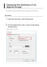
Страница 494: ...ed Press and to move the cutting carriage Press and to move the material Procedure This function can be used when the screen shown below is displayed Press ENTER and one of the cursor keys and at the...

Страница 495: ...ad Crop Marks Cannot Be Read Cutting Results Are Not Clean The Results of Cutting Are Displaced When Using the Printing and Cutting Function The Machine Cuts the Same Area Twice Frequently Asked Quest...

Страница 496: ...marks cannot be detected if decorations or colors are on the material Crop marks also may not be detected on glossy material even if it is white Materials That Can Be Used for Printing and Cutting Doe...

Страница 497: ...deg Be sure to set the ROTATE menu to 0deg when using crop marks Crop marks cannot be read if this is set to 90deg Setting the Direction of the Coordinate Axis for Cutting ROTATE Is the machine expose...

Страница 498: ...cified by the software match those specified on the machine Manual mode On the machine correctly set the distance specified by the software Are the crop marks at the correct positions If the angle for...

Страница 499: ...uality to HEAVY Setting Cutting Quality QUALITY When using roll material was the amount of material to be cut pulled out before performing cutting If cutting is performed without pulling out the mater...

Страница 500: ...the Cut Setting screen in Plug in for Illustrator the number is added to the number of cuts Is the machine s OVERLAP setting a number from 1 to 9 Set the machine s OVERLAP setting to OFF Cutting in th...

Страница 501: ...Illustrator Installation Procedure Install from the following link http startup rolanddg com Supported Versions For information regarding the latest supported versions visit the Roland DG Corp website...

Отзывы: