3 Replacement of Main Parts
23
3
5
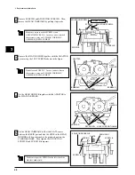
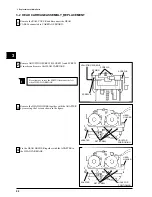
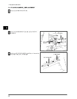
Make sure to put the SPRING to the left side of the
HEAD CARRIAGE.
SCREW A
SPRING
SCREW B
SCREW B
6
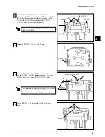
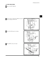
Loosen the SCREW C shown in the figure.
Tighten SCREW A. Make sure that the PLATE is not
tilting.
Adjust the ADJUSTING SCREW A until it makes contact
with the PLATE so that the clearance shown in the figure
will be 9.2 mm—10.6 mm (STANDARD : 9.7 mm).
7
8
9.2 mm
~10.6 mm
SCREW A
PLATE
SCREW C
RESIN PART
PLATE
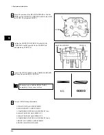
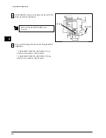
Put the HEAD CARRIAGE so that the PLATE comes
between the RESIN part and also the HOLE in the HEAD
HOLDER will be positioned to the projected part on the
CARRIAGE BASE. Then tighten the ADJUSTING
SCREW B and SCREW A & B temporary.
ADJUSTING SCREW A
This adjustment is necessary to make the HEAD come
straight down on the PLATEN DAMPER.It might
cause broken ribbon or twisted ribbon if not adjusted.
Contact part
ADJUSTING SCREW B
Содержание Color Camm Pro PC-60
Страница 4: ... MEMO ...
Страница 6: ...2 1 Structure Spare Parts 1 1 2 FRAME 1 ...
Страница 8: ...4 1 Structure Spare Parts 1 1 3 FRAME 2 ...
Страница 88: ...84 4 Adjustment 4 MEMO ...


