background image

8

  1  Structure & Spare Parts

1

1-8  ACCESSORIES

ENGLISH

JAPANESE

10

6

1

3

4

9

8

2

5

7

1-7  STAND

1

2

1

2

2

6

4

4

1

8

5

7

3

3

4

5

6

7

8

11

PARTS LIST -Main Parts-

Parts No.

Parts Name

1

7448502000

STAND LEG ASS'Y PNS-135

2

22715142

STAY,PNS-135

3

7448503000

SHAFT SHEET ASS'Y PNS-135

4

21985114

BRACKET ,MOUNTING FIX.PNS-135

5

21665104

HANGER,L PNS-186

6

21665105

HANGER,R PNS-186

7

11499108

SCREW,STOPPER RETAINING PNS186

8

22135316

STOPPER,PNS-186

PARTS LIST   -Supplemental Parts-

Parts Name

1

TOOL  HEXAGONAL WRENCH 5


2

TOOL  HEXAGONAL WRENCH 4


3

TOOL  HEXAGONAL WRENCH 3


4

TOOL  HEXAGONAL WRENCH 2.5


5

BOLT  HEXAGONAL SOCKET HEAD  

BC  6X70

6

SCREW  HEXAGONAL CAP 

BC  6X15

7

SCREW  HEXAGONAL CAP 

BC  4X8

8

SCREW  HEXAGONAL FLAT HEAD   

Cr  4X8

PARTS LIST -Main Parts-

Parts No.

Parts Name

1

23495124

 AC CORD 3ASL/100 240VA 10A SAA

2

13499111

 AC CORD H05VV-F 240VE 10A S

3

13499109

 AC CORD SJT 117V 10A 3PVC

4

23495214

 AC CORD VCTF 100V 7A 3P-S

5

23495125

 AC-CORD H05VV 230V 10A S

6

13499209

 ADAPTER PLUG  (100V)

7

22605249

 CARTON,PC-60(PAD SET)

8

26015155

 MANUAL,USE EN PC-60

9

26015156

 MANUAL,USE JP PC-60

10

22695102

 PEN HEAD CLEANER

11

21475105

 SHEET,HEAD CLEANER PC-50

Содержание Color Camm Pro PC-60

Страница 1: ... Special Tool 39 4 2 Service Mode 40 4 3 Factory Mode 41 4 4 Faunction Mode 43 4 5 HOW TO UPGRADE FIRMWARE 45 4 6 TOOL HEIGHT ADJUSTMENT 46 4 7 TOOL PRESSURE ADJUSTMENT 48 4 8 HEAD VOLTAGE ADJUSTMENT 51 4 9 AUTO THERMAL HEAD DENSITY ADJUSTMENT 53 4 10 MANUAL THERMAL HEAD DENSITY ADJUSTMENT 57 4 11 HEAD POSITION ADJUSTMENT 1 61 4 12 HEAD POSITION ADJUSTMENT 2 63 4 13 PRINT CUT OFFSET ADJUSTMENT 65 ...

Страница 2: ...symbol alerts the user to important instructions or warnings The specific meaning of the symbol is determined by the design contained within the triangle The symbol at left means danger of electrocution About the Symbols The symbol alerts the user to items that must never be carried out are forbidden The specific thing that must not be done is indicated by the design contained within the circle Th...

Страница 3: ... Affixed to the Unit These labels are affixed to the body of this product The following figure describes the location Electric charge Do not touch when power is on The wiring terminal intended for connecetiion of the protective earthing conductor associated with the supply wiring Do not disconnect the cable of this terminal except the time of replacement Turn off the main power SW before servicing...

Страница 4: ... MEMO ...

Страница 5: ...9 GUIDE CUTTER PC 60 9 22505284 LABEL COLOR CAMM PRO PC60 760 11 7435220020 PANEL BOARD ASS Y 12 7435217010 PANELKEY BOARD ASS Y 13 22665236 SHEET PANEL SW PC 60 14 12369446 CS 2 CLIP PARTS LIST Supplemental Parts Parts Name 3 LABEL CAMM 1 WARNING 4 LABEL CAUTION PAD PC 60 No 766 5 LABEL DIP SW PC60 6 SCREW BINDING HEAD Cr 3X8 7 SCREW BINDING HEAD BC 3X6 8 SCREW P TIGHT BINDING HEAD BC 3X6 9 SCREW...

Страница 6: ...2 1 Structure Spare Parts 1 1 2 FRAME 1 ...

Страница 7: ...RING 217 723 27 21975126 PULLEY HD43 44S16 B21C26 5 28 15229506 SENSOR INTERRUPTER GP1A05A5 29 22145122 SHAFT STAY NO 1 214 122 30 22295144 SHAFT PULLEY PC 60 31 22175149 SPRING CARTRIDGE BACKUP PC 60 32 22175148 SPRING CARTRIDGE HOLDER PC 60 33 22175150 SPRING COVER F PC 60 34 22175151 SPRING SET COVER F PC 60 35 22035318 STAND OF IDLE PULLEY 36 22715130 STAY FRAME GUIDE PC 60 37 22715129 STAY HE...

Страница 8: ...4 1 Structure Spare Parts 1 1 3 FRAME 2 ...

Страница 9: ...PC 60 25 21545123 PAD RUBBER R PC 60 26 15229705 PHOTO INTERRUPTER GP1A71A1 27 22145831 PIN NO 1 214 831 28 22175289 PINCH ROLL SPRING 29 22175877 PINCH ROLLER 30 22055339 PLATE G ORIGIN PC 60 31 22055338 PLATE SHAFT PC 60 32 22175871 ROLLER FD12 S4 B4 C4 0 33 15229505 SENSOR INTERRUPTER GP2A25 34 22145393 SHAFT JOINT PNC 960 35 22295145 SHAFT SQUARE PC 60 36 22295143 SHAFT WITH G ROLLER PC 60 37 ...

Страница 10: ...SB 3 15 100 110 117V 14 22465115 HEAT SINK PC 60 15 12189835 HOLDER FUSE BM SS 1 14 16 7435214000 MAIN BOARD ASS Y 17 13129170 POWER SW AJ7201B 18 22355168 RUBBER FOOT PL 10J65 19 7435217030 TRANS BOARD ASS Y 20 22455112U0 TRANSFORMER PW PC 60 21 23505898 WIRE B GRX 410 22 23505899 WIRE C GRX 410 23 23505367 CABLE ASSY MECHA SENS PC 60 PARTS LIST Supplemental Parts Parts Name 1 LABEL FLASH LIGHTIN...

Страница 11: ...0 11 22035122 STAND CUT CARRIAGE PC 60 12 22715123 STAY CARRIAGE BOARD PC 60 PARTS LIST Supplemental Parts Parts Name 1 BINDER T 18L 2 CUSHION FELT 30X8X3 3 SCREW W SEMS BC 3X6 4 TAPE FILAMENT 12X30 5 TAPE NITTO 500 CUT WHEN USING 20X30 PARTS LIST Main Parts Parts No Parts Name 1 21905123 ADAPTER P HEAD HOLDER PC 60 2 22805218 ASS Y CARRIAGE THERMAL PC 60 3 21655144 HOLDER PRINT HEAD 2 PC 60 4 221...

Страница 12: ...rts Name 1 TOOL HEXAGONAL WRENCH 5 2 TOOL HEXAGONAL WRENCH 4 3 TOOL HEXAGONAL WRENCH 3 4 TOOL HEXAGONAL WRENCH 2 5 5 BOLT HEXAGONAL SOCKET HEAD BC 6X70 6 SCREW HEXAGONAL CAP BC 6X15 7 SCREW HEXAGONAL CAP BC 4X8 8 SCREW HEXAGONAL FLAT HEAD Cr 4X8 PARTS LIST Main Parts Parts No Parts Name 1 23495124 AC CORD 3ASL 100 240VA 10A SAA 2 13499111 AC CORD H05VV F 240VE 10A S 3 13499109 AC CORD SJT 117V 10A...

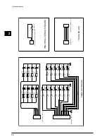
Страница 13: ...ANEL BOARD L N PANELKEY BOARD K COVER STS ORG GRIT FLASHROM MTD 2005 X 5 FAN DRIVE 2SK973 M BOARD RS232C DRIVER DRIVER SUB BOARD ASSY PANEL CARRIAGE MAIN BOARD ASSY PANELSUB BOARD ASSY PANELKEY TRANS PINCHROLL SENSOR SENSOR INTERRUPTER GP2A25 SENSOR INTERRUPTER GP2A25 SENSOR INTERRUPTER GP1A71A1 SENSOR INTERRUPTER GP1A71A1 SENSOR INTERRUPTER GP1A71A1 SENSOR INTERRUPTER GP1A05A5 TRANS BOARD MTR CN8...

Страница 14: ...IC 2 15189105 MTD2005 Solenoid Motor Driver IC 3 15189105 MTD2005 Carriage Motor Driver IC 4 15189105 MTD2005 Ribbon Winding Driver IC 14 15189105 MTD2005 Grit Motor Driver IC 15 15189105 MTD2005 Head UP DOWN Driver IC 19 15199111 SI 3050J 5V Regulator IC IC 20 15199112 LM2576HVT HV Regulator IC IC 21 15159102 SN75LBC775 RS 422 IC 24 15169146 SN74ACT1284 Centronics IC 27 15169146 SN74ACT1284 Centr...

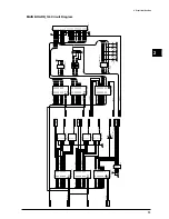
Страница 15: ...3 21 D4 24 D5 26 D6 28 D7 30 D8 16 D9 18 D10 20 D11 22 D12 25 D13 27 D14 29 D15 31 CE 12 OE 14 RY BY 2 WE 43 RESET 44 BYTE 33 IC18 MBM 29F400BA VCC A1 A2 A3 A4 A5 A6 A7 A8 A9 A10 A11 A12 A13 A14 A15 A16 A17 A18 D0 D1 D2 D3 D4 D5 D6 D7 D8 D9 D10 D11 D12 D13 D14 D15 VCC CP16 CE0 1u C46 CE0 1u C47 CE0 1u C48 CE0 1u UDENA UDENB UDENA UDENB A19 A19 FROM A18 A19 MODE FAN FAN 5 6 IC22C SN74LS14NS A 2 B 3...

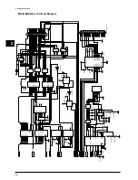
Страница 16: ...6 7 8 9 10 11 12 13 14 15 16 17 18 19 20 CN5 IL FPC 20ST N SOL RFA RFB RFC RFD RFD RFC RFB RFA SOL SOL UDA UDB UDC UDD UDD UDC UDB UDA SOL VCC 5 5 4 4 6 6 3 3 7 7 2 2 8 8 1 1 RA15 EXBS8V103J 5 5 4 4 6 6 3 3 7 7 2 2 8 8 1 1 RA16 EXBS8V101J C33 CE1000p C34 CE1000p C35 CE1000p VCC PRSENS TEMP RELED RETR RC2LED RC2TR RC1LED RC1TR VCC VCC ETCC RD WRL WRH RESET ETCC RD WRL WRH RESET 5 4 GND 2 OUT 3 NC 1...

Страница 17: ...Q7 16 D8 18 Q8 19 CLK 11 CLR 1 IC32 SN74HC273NS D0 D1 D2 D3 D4 D5 D6 D7 D1 3 Q1 2 D2 4 Q2 5 D3 7 Q3 6 D4 8 Q4 9 D5 13 Q5 12 D6 14 Q6 15 D7 17 Q7 16 D8 18 Q8 19 CLK 11 CLR 1 IC33 SN74HC273NS D0 D1 D2 D3 D4 D5 D6 D7 D0 3 Q0 2 D1 4 Q1 5 D2 7 Q2 6 D3 8 Q3 9 D4 13 Q4 12 D5 14 Q5 15 D6 17 Q6 16 D7 18 Q7 19 OE 1 CLK 11 IC31 SN74LS374NS MTRX MTRX MTRC MTRC RESET RESET D1 2 D2 3 D3 4 D4 5 D5 6 D6 7 D7 8 D8...

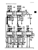
Страница 18: ...7 2B 6 3A 11 3Y 9 3B 10 4A 14 4Y 12 4B 13 G 15 A B 1 IC26 SN74LS257NS ACK BSY D0 3 Q0 2 D1 4 Q1 5 D2 7 Q2 6 D3 8 Q3 9 D4 13 Q4 12 D5 14 Q5 15 D6 17 Q6 16 D7 18 Q7 19 OE 1 CLK 11 IC8 SN74LS374NS D0 D1 D2 D3 D4 D5 D6 D7 R8 100 D 0 15 D 0 15 nAutoFd nSelectIn nInit CENTRO CENTRO C1 10 C1 12 C2 13 C2 14 V 11 V 15 T1OUT 2 R1IN 7 T2OUT 1 R2IN 3 T3OUT 24 R3IN 23 T4OUT 20 R4IN 16 T1IN 5 R1OUT 6 T2IN 18 R2...

Страница 19: ... 2 CN13 5267 02A R12 0 68 1W L1 RCH895 181K FAN FAN MTR VCC CP4 CE0 1u VCC VCC 25 ALM 3 PHA 5 PHB 23 ENA A 6 ENA B 22 VREFA 2 VREFB 26 CR 4 NC 19 VSA 1 VSB 27 VMMA 8 VMMB 20 OUT1 10 OUT2 12 OUT3 14 OUT4 18 LG A 7 LG B 21 DECAY 24 NC 9 NC 15 NC 16 IC15 MTD 2005 RFPA RFPB RFPA RFPB RFA RFB RFC RFD RFA RFB RFC RFD RFPWR RFPWR MTR VCC VCC R18 10K C32 CE4700p CP2 CE0 1u VCC VCC 25 ALM 3 PHA 5 PHB 23 EN...

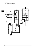
Страница 20: ...700u 16V R72 10K 1 4W D6 D1FL20U VI 5 VO 3 SENCE 4 IC19 SI 3050J C58 470u 16V CP19 CE0 1u 1 2 3 4 CN14 B4P VH CP18 CE0 1u C55 4700u 50V R75 18K R74 1K VR 1 10KVR L2 CL02BE181 D8 D5S6M D7 D1FL20U HEAD VH VIN 1 OUT 2 IC20 LM 2576HVT Q13 2SB1551 R70 4 7K 1 4W R71 10K 1 4W HEAD D4 D1FL20U POWER POWER R73 10K 1 4W 1 2 3 CN12 5267 03A D5 ZD3 3 POWER POWER 3 1 2 Q14 DTC 114EK C59 CE0 1u 2 3 2 3 ON OFF GN...

Страница 21: ...10 11 12 13 14 15 16 17 18 19 20 21 22 23 24 25 26 CN1 IL FPC 26ST N LIN6 LIN7 LIN8 LIN9 LIN10 LIN11 LIN12 LIN0 LIN1 LIN2 LIN3 LIN4 LIN5 1 3 2 D1 DAN202K 1 3 2 D5 DAN202K 1 3 2 D4 DAN202K 1 3 2 D3 DAN202K VR1 10KVR R1 4 7K VCC 1 3 2 D2 DAN202K MI0 MI1 MI2 MI3 MI0 MI1 MI2 MI3 MI0 MI1 1 2 3 4 5 6 CN2 53014 06 VCC VCC VCC B1 5 E 4 B2 3 C1 1 C2 2 Q1 FMA9 B1 5 E 4 B2 3 C1 1 C2 2 Q2 FMA9 B1 5 E 4 B2 3 C...

Страница 22: ...P D14 1SS133 D15 1SS133 D16 1SS133 D17 1SS133 D18 1SS133 D19 1SS133 D20 1SS133 D21 1SS133 MI 0 MI 1 MI 2 MI 3 MI 0 MI 1 MI 2 MI 3 MI 0 MI 1 MI 2 MI 3 1 2 3 4 5 6 CN1 CABLE ASSY KEY PC 60 PANELKEY BOARD SW 1 RD17BS3040 1 2 CN1 CABLE ASSY PINCH SENS PC 60 PINCHROLL SENSOR BOARD 1 2 3 4 TRANS FORM 1 2 3 4 CABLE ASSY POWER PC 6 0 TRANS BOARD EVQ21307K EVQ21307K EVQ21307K EVQ21307K EVQ21307K EVQ21307K ...

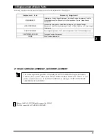
Страница 23: ... you have touched this screw fix the HEAD CARRIAGE by refering to 3 2 HEAD CARRIAGE ASSEMBLY_REPLACEMENT Replacement Parts Necessary Adjustment MAIN BOARD Initialization Head Voltage Adjustment Cartridge Position Adjustment Print Cut Offset Adjustment Tool Pressure Grit Compensation Thermal Head Density Adjustment HEAD CARRIAGE Head Voltage Adjustment Head Density Adjustment Cartridge Position Adj...

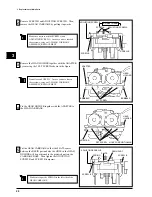
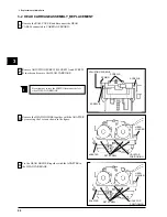
Страница 24: ...ve the HEAD CARRIAGE by pulling it upwards Make sure not to touch the SCREW A and ADJUSTING SCREW A In case you have touched these screws carry out 3 2 HEAD CARRIAGE ASSEMBLY_REPLACEMENT SCREW A ADJUSTING SCREW B SCREW B SCREW B DO NOT TOUCH Do not loosen SCREW C In case you have loosen these screws carry out 3 2 HEAD CARRIAGE ASSEMBLY_REPLACEMENT SET SCREW HEAD HOLDER 4 Fix the HEAD HOLDER togeth...

Страница 25: ...them with INSULOCK TIE Make sure not to fold the HEAD CABLE completely It may cause cut line NG GOOD 6 Carry out the following adjustments 1 HEAD VOLTAGE ADJUSTMENT 2 HEAD DENSITY ADJUSTMEJNT 3 CARTRIDGE POSITION ADJUSTMENT 1st 4 HEAD POSITION ADJUSTMENT 2 5 CARTRIDGE POSITION ADJUSTMENT 2nd 6 PRINT CUT OFFSET ADJUSTMENT 7 PRINT LENGTH INITIALIZE 7 Try printing test If you have twisted ribbon carr...

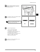
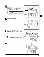
Страница 26: ...ng the 3 screws shown in the figure ADAPTER 2 Remove ADJUSTING SCREW B SCREW A and SCREW B in order and remove the HEAD CARRIAGE Be careful not to lose the SPRING located at the left side of HEAD CARRIAGE SCREW A SPRING SCREW B SCREW B SET SCREW HEAD HOLDER 4 Fix the HEAD HOLDER together with the ADAPTER to the HEAD CARRIAGE ADAPTER SET SCREW HEAD HOLDER HOLE FOR POSITIONING HOLE FOR POSITIONING A...

Страница 27: ...e figure will be 9 2 mm 10 6 mm STANDARD 9 7 mm 7 8 9 2 mm 10 6 mm SCREW A PLATE SCREW C RESIN PART PLATE Put the HEAD CARRIAGE so that the PLATE comes between the RESIN part and also the HOLE in the HEAD HOLDER will be positioned to the projected part on the CARRIAGE BASE Then tighten the ADJUSTING SCREW B and SCREW A B temporary ADJUSTING SCREW A This adjustment is necessary to make the HEAD com...

Страница 28: ...USTMENT 3 CARTRIDGE POSITION ADJUSTMENT 1st 4 HEAD POSITION ADJUSTMENT 1 5 HEAD POSITION ADJUSTMENT 2 6 CARTRIDGE POSITION ADJUSTMENT 2nd 7 PRINT CUT OFFSET ADJUSTMENT 8 PRINT LENGTH INITIALIZE 10 Tighten the ADJUSTING SCREW B so that HEAD CARRIAGE would be parallel to the GUIDE RAIL And tighten up SCREW B ADJUSTING SCREW B SCREW B 9 Adjust the position of the HEAD CARRIAGE so that the RESIN part ...

Страница 29: ...E and SOLENOID WIRE 3 Remove the SCREW A and SCREW B in order and remove the TOOL CARRIAGE 4 Tighten up SCREW B and SCREW A in order to fix the TOOL CARRIAGE Then carry out the following adjustments 1 TOOL HEIGHT ADJUSTMENT 2 TOOL PRESSURE ADJUSTMENT 3 PRINT CUT OFFSET ADJUSTMENT SOLENOID WIRE PINCH ROLLER SENSOR WIRE 1 SCREW A 2 SCREW B 2 SCREW A 1 SCREW B ...

Страница 30: ... the RIGHT SIDE COVER 2 Remove the RUBBER MAT and slide out the PLATEN DAMPER 3 Put the new PLATEN DAMPER so that there is looseness in 4 directions front rear left and right 3 4 PLATEN DAMPER_REPLACEMENT PLATEN DAMPER RUBBER MAT PLATEN DAMPER ...

Страница 31: ...RM_FIXING 1 Remove the HEAD CARRIAGE 2 Move the front part of the HEAD CARRIAGE towards the front by rotating the WHITE STICK 3 Put the HEAD ARM as shown in the figure 4 Put the SPRING as shown in the figure WHITE STICK HEAD ARM HEAD ARM SPRING ...

Страница 32: ...HEAD ARM to the HEAD CARRIAGE 6 Make sure that the HEAD ARM moves smoothly Carry out the following adjustments after fixing the HEAD CARRIAGE 1 CARTRIDGE POSITION ADJUSTMENT 1st 2 HEAD ALIGNMENT ADJUSTMENT 3 CARTRIDGE POSITION ADJUSTMENT 2nd 4 PRINT CUT OFFSET ADJUSTMENT HEAD ARM SPRING ...

Страница 33: ...NT COVER 2 Open the FRONT COVER BASE and remove the CARTRIDGE HOLDER 3 Open the LEFT and RIGHT ARM and remove the CARTRIDGE PLATE together with the RIBBON LEVER 4 Pull out the PIN and remove the ARM and SPRING SPRING ARM PIN CARTRIDGE HOLDER SCREWS FRONT COVER BASE ARM ARM CARTRIDGE PLATE RIBBON LEVER ...

Страница 34: ...OLDER BASE Put CEMEDINE SUPER X NO 8008 on top of the PIN 7 Put the CARTRIDGE PLATE together with the RIBBON LEVER Be careful with the direction of the ARM Make sure to put the ARM and SPRING in order SPRING ARM PIN HOLDER BASE RIGHT SIDE LEFT SIDE ARM HOLDER BASE SPRING PIN CEMEDINE SUPER X NO 8008 SPRING ARM CARTRIDGE PLATE RIBBON LEVER ...

Страница 35: ...GE HOLDER BASE from the right side has the BLACK TAPE put to it to prevent malfunction of the MEDIA SENSOR CARTRIDGE HOLDER SCREWS FRONT COVER BASE BLACK TAPE CARTRIDGE HOLDER BASE 8 Make sure that both left and right ARM will open equally If not bend the holder slightly downwards to adjust it HOLDER Bend slightly downwards ...

Страница 36: ... 1 Remove the RAIL COVER LEFT RIGHT SIDE COVER and REAR APRON 2 Remove the PINCH ROLLER SPRING and remove the 2 screws shown in the figure 3 Untighten the 4 screws and remove the BRACKET 4 Remove the INNER COVER 1 SPRING 2 SCREWS SCREWS SCREWS BRAKET INNER COVER ...

Страница 37: ...OLLER SHAFT 6 Remove the BUSH located at the left end of PINCH ROLLER SHAFT 7 Pull out the PINCH ROLLER SHAFT from the REAR SIDE of the machine 8 Remove the STOPPER and replace the PINCH ROLLER ASSY PINCH ROLLER ASSY PINCH ROLLER SHAFT STOPPER STOPPER PINCH ROLLER SHAFT E RING BUSH ...

Страница 38: ...Be careful with the direction of the PINCH ROLLER and the position of the MAGNET when installing the PINCH ROLLER ASSY 10 Put the STOPPER as shown in the figure STOPPER STOPPER LEFT END GRIT RIGHT END GRIT MAGNET PINCH ROLLER RED MARKING ...

Страница 39: ..._REPLACEMENT 1 Remove the RAIL COVER and LEFT RIGHT SIDE COVER 2 Detach the WIRE from the CARRIAGE BASE 3 Loosen SCREW A and SCREW B in order and loosen the WIRE TENSION 4 Remove the WIRE as shown in the figure WIRE SCREW WIRE SCREWS A SCREW B ...

Страница 40: ...Remove the MOTOR BRACKET 6 Remove the DRIVER PULLEY from the MOTOR BRACKET 7 Loosen the 4 screws and pull out the WIRE 8 Put the new WIRE to the DRIVE PULLEY and fix it to the MOTOR BRACKET WIRE SCREWS SCREWS BRAKET SCREW WIRE SCREW WIRE ...

Страница 41: ...e WIRE around the DRIVE PULLEY from bottom to the top 11 Rotate the DRIVE PULLEY until the WIRE comes to its center 12 Fix the TOOL CARRIAGE at the center part of the GUIDE RAIL Make sure the WIRE won t overlap DRIVE PULLEY WIRE WIRE DRIVE PULLEY SCREWS BRAKET SCREW WIRE projection ...

Страница 42: ...remove the slack in the WIRE 14 Adjust the WIRE TENSION 3 9 MOTOR_FIXING 1 Fix the GRIT MOTOR along with the BRACKET so that there is no looseness or too much load 2 Fix the CARRIAGE MOTOR so that there is no looseness or too much load GUIDE RAIL CARRIAGE GRIT SIDE SCREWS BRACKET SCREWS CARRIAGE SIDE ...

Страница 43: ...Tool name WHITE DUMMY PEN Tool Height Adjustment Purpose Tool Pressure Adjustment Tool No ST 011 Tool name TENSION METER Wire Tension Adjustment Purpose Tool No ST 012 Tool name DIAL TENSION METER DT 30 30g Tool Pressure Adjustment Purpose Tool No ST 025 Tool name HEAD VOLTAGE ADJUSTMENT TOOL Head Voltage Adjustment Purpose Tool No ST 035 Tool name RS 422 LOOP BACK CONNECTOR Serial Interface Check...

Страница 44: ...Y Push the keys in order from the top key to the bottom key PIECE LED ON ROLL LED ON PIECE LED BLINK ROLL LED BLINK DIP SW Turn off all the DIP SW Turn on the DIP SW in order from bit 1 to bit 10 PIECE LED ON ROLL LED ON PIECE LED BLINK ROLL LED BLINK This mode is to check the SENSORS and FAN Following LED will light when sensor is ON FRONT PAPER SENSOR PIECE LED REAR PAPER SENSOR ROLL LED FRONT C...

Страница 45: ...EET TYPE key PIECE ROLL LED WILL BLINK NG PIECE ROLL LED WILL BE ON OK PRINTED LENGTH INITIALIZE Printed length and cleaning counts will be set to 0 Enter the FACTORYMODE and selet PRINTED LENGTH INITIALIZE Push SHEET TYPE key PIECE ROLL LED WILL BLINK NG PIECE ROLL LED WILL BE ON OK LED MODE PIECE EEROM INITIALIZE ROLL PRINTED LENGTH INITIALIZE CARTRIDGE HOLDER NO 1 PRINT CUT OFFSET ADJUSTMENT CA...

Страница 46: ...ION This mode is used for compensating Media Feeding rate Refer to the ADJUSTMENT SECTION for details GRIT ECCENTRICITY ADJUSTMENT This mode is used for Adjusting Grit Eccentricity Refer to the ADJUSTMENT SECTION for details CARTRIDGE POSITION ADJUSTMENT This mode is used for Adjusting Cartridge Position Refer to the ADJUSTMENT SECTION for details THERMAL HEAD DENSITY ADJUSTMENT This mode is used ...

Страница 47: ...x 41 Min 343 Grit Distance 8 Eccentricity Amount 0 Number 0 Head ID B06 0032 Density Adjust 1 1 0 0 0 0 0 0 0 0 0 0 0 0 0 0 0 0 0 0 0 0 0 0 0 0 1 0 0 1 Stitch Adjust Upper 0 Lower 0 On Board Dip SW 1 X0XX 4 User settings User Dip SW 1 XXXXXXXXXX 10 Line Space 0dot Total Printed Length Head Temperature Amount set by Print Cut Offset Adjustment Amount set by Cartridge Position Adjustment Indicates t...

Страница 48: ...r CUT TEST keys Set the Black Ribbon and Media Lower the Sheet Loading Lever to print Turn off the sub power SW to end Connection 2 TxD 3 RxD 5 CTS 20 DTR Connection 1 HskoA DTR 2 HskiA CTS 3 TXDA 5 RXDA 6 TXDA 8 RXDA TEST PATTERN CARTRIDGE HOLDER LED NO 1 NO 2 NO 3 NO 4 NO 5 NO 6 3mm pitch straight line OFF OFF OFF OFF OFF OFF Dithering Test Pattern ON OFF OFF OFF OFF OFF 100 Dithering Pattern OF...

Страница 49: ...LED become ON and CARTRIDGE HOLDER 2 LED blinks 3 Open the download bat from MS DOS Type download and press RETURN key 4 Turn off the MAIN POWER SW to end when all CARTRIDGE HOLDER LEDs blink It is necessary to prepare the followings to upgrade the FIRMWARE 1 FIRMWARE DISK 2 PC with MS DOS 3 PARALLEL CABLE Some PCs can not use the BAT FILE Please refer to the ReadMe File in the FIRMWARE DISK ...

Страница 50: ...OL CARRIAGE BED and GUIDE RAIL It is necessary to enter TOOL PRESSURE ADJUSTMENT MODE in the FACTORY MODE to perform this adjustment ROLAND SPECIAL TOOL ST 006 is used for this adjustment TOOL PRESSURE ADJUSTMENT MODE SHEET TYPE key CUT TEST key BASE POINT key or key or key Adjust Tool Pressure MIN MODE MAX MODE Move Tool DOWN CUT TEST key Save Settings All CARTRIDGE HOLDER LED will be ON All CART...

Страница 51: ...ET TYPE and BASE POINT keys and enter the FACTORY MODE Select CARTRIDGE HOLDER 2 with or keys and press SHEET TYPE key to enter the TOOL PRESSURE ADJUSTMENT MODE 4 Move the TOOL CARRIAGE to the 3 positions shown in the figure Carry out the procedure mentioned in 5 at the position where the clearance between the pen tip and the BED is the smallest among the 3 ST 006 CARRIAGE ASSEMBLY ADJUSTING SCRE...

Страница 52: ...cutting This adjustment must be performed after replacement of the TOOL CARRIAGE BED and GUIDE RAIL It is necessary to enter TOOL PRESSURE ADJUSTMENT MODE in the FACTORY MODE to perform this adjustment ROLAND SPECIAL TOOL ST 002 ST 006 and ST 012 is used for this adjustment TOOL PRESSURE ADJUSTMENT MODE SHEET TYPE key CUT TEST key BASE POINT key or key or key Adjust Tool Pressure MIN MODE MAX MODE...

Страница 53: ...e the SLIDE VOLUME for TOOL PRESSURE at the right side of the machine to MAX MAX MODE CARTRIDGE HOLDER LED ON MIN MODE CARTRIDGE HOLDER LED OFF ST 002 CARRIAGE ASSEMBLY BED To enter For selection 4 Move the TOOL CARRIAGE to the position where the TOOL HIGHT has been adjusted by hand Press CUT TEST key to move the tool down Turn on the MAIN POWER SW while pressing POWER SHEET TYPE and BASE POINT ke...

Страница 54: ... TOOL PRESSURE so that it will be 25 35gf with and keys Press SHEET TYPE key to save the settings Turn off the MAIN POWER SW to end ST 012 CARRIAGE ASSEMBLY BED 6 Select MIN MODE MAX and MIN can be selected by pressing the BASE POINT key Then move the SLIDE VOLUME for TOOL PRESSURE at the right side of the machine to MIN MAX MODE CARTRIDGE HOLDER LED ON MIN MODE CARTRIDGE HOLDER LED OFF ...

Страница 55: ...r the FAN stops HEAD VOLTAGE drops down when FAN is rotating ST 025 CN12 CN12 Make sure to use ST 025 If not it may result in the breakage of the HEAD HEAD VOLTAGE ADJUSTMENT is designed to level the manufacturing tolerance of consumption in each HEAD by adjusting the voltage This adjustment must be performed after replacement of the HEAD CARRIAGE and MAIN BOARD ROLAND SPECIAL TOOL ST 025 is used ...

Страница 56: ...Adjustment 4 5 The HEAD VOLTAGE is written on top of the HEAD CARRIAGE SPRING SCREWS 29 8V 4 Adjust VR1 on the MAIN BOARD so that the voltage will be the one written on the top part of the HEAD CARRIAGE VR1 ...

Страница 57: ...p and setting the heating time of each group one by one There are 2 ways of performing this adjustment 1 AUTO ADJUSTMENT 2 MANUAL ADJUSTMENT AUTO ADJUSTMENT can be done by sending the HEAD data file TEI for each HEAD using special software PC60SPF EXE Spare HEAD will be supplied with the data file and the software MANUAL ADJUSTMENT can also be done by setting 30 parameters manually from the panel ...

Страница 58: ...DE RESET MODE GROUP SELECTION MODE Select GROUP to be adjusted SETTING MODE Change parameters for HEAD DENSITY Save Settings THERMAL HEAD DENSITY ADJUSTMENT MODE STITCHING ADJUSTMENT MODE Send data from PC STITCHING ADJUSTMENT for TOP EDGE STITCHING ADJUSTMENT for BOTTOM EDGE Change parameters for TOP STITCHING ADJUSTMENT Change parameters for BOTTOM STITCHING ADJUSTMENT Save Settings Save Setting...

Страница 59: ...data 2 Data file for the HEAD TEI 3 README TXT 5 Send data file from MS DOS by typing as below PC60SPF L TEI is the serial number of the HEAD It is also written on the HEAD as shown in the figure Example B05 0051 PTMTM3207A 719A10 Serial Number B05 0051 6 When the AUTOMATIC ADJUSTMENT is done properly CARTRIDGE HOLDER LED will be OFF from 1 to 6 in order If NG PC 60 repeats the following indicatio...

Страница 60: ...ff the MAIN POWER SW and start from the beginning 8 The parameters for the HEAD DENSITY ADJUSTMENT is put on the GUIDE RAIL Grit Distance 8 Eccentricity Amount 0 Number 0 Head ID B06 0032 Density Adjust 1 1 0 0 0 0 0 0 0 0 0 0 0 0 0 0 0 0 0 0 0 0 0 0 0 0 1 0 0 1 Stitch Adjust Upper 0 Lower 0 ...

Страница 61: ...JUSTMENT MODE STITCHING ADJUSTMENT MODE Send data from PC STITCHING ADJUSTMENT for TOP EDGE STITCHING ADJUSTMENT for BOTTOM EDGE Change parameters for TOP STITCHING ADJUSTMENT Change parameters for BOTTOM STITCHING ADJUSTMENT Save Settings Save Settings POWER key key or keys or keys SHEET TYPE key CUT TEST key COLOR LED will be ON key SHEET TYPE key CARTRIDGE HOLDER 1 3 5 and CARTRIDGE HOLDER 2 4 ...

Страница 62: ...he POWER key until POWER and FRONT COVER LED start blinking to enter the STITCHING ADJUSTMENT MODE 3 2 4 Press CUT TEST key to enter the MANUAL ADJUSTMENT MODE During this mode COLOR LED will be ON Reset the settings for THERMAL HEAD DENSITY ADJUSTMENT to 0 To enter the RESET MODE press key CARTRIDGE HOLDER LED 1 3 5 and CARTRIDGE HOLDER LED 2 4 6 will blink alternately To carry out press SHEET TY...

Страница 63: ...ER LED NO 1 2 3 4 5 15 ON ON ON ON OFF 16 OFF OFF OFF OFF ON 17 ON OFF OFF OFF ON 18 OFF ON OFF OFF ON 19 ON ON OFF OFF ON 20 OFF OFF ON OFF ON 21 ON OFF ON OFF ON 22 OFF ON ON OFF ON 23 ON ON ON OFF ON 24 OFF OFF OFF ON ON 25 ON OFF OFF ON ON 26 OFF ON OFF ON ON 27 ON ON OFF ON ON 28 OFF OFF ON ON ON 29 ON OFF ON ON ON 6 8 Set the parameters by pressing or keys Press SHEET TYPE key to save the se...

Страница 64: ...N POWER SW to finish the adjustment 10 The parameters for the HEAD DENSITY ADJUSTMENT is put on the GUIDE RAIL Grit Distance 8 Eccentricity Amount 0 Number 0 Head ID B06 0032 Density Adjust 1 1 0 0 0 0 0 0 0 0 0 0 0 0 0 0 0 0 0 0 0 0 0 0 0 0 1 0 0 1 Stitch Adjust Upper 0 Lower 0 ...

Страница 65: ...ality by aligning the HEAD to land straight down on the PLATEN It is necessary to avoid BLURRY PRINT BROKEN RIBBON and TWISTED RIBBON This adjustment must be performed after replacement of the HEAD CARRIAGE 2 SCREW B 3 Loosen the SCREW C shown in the figure SCREW C ADJUSTING SCREW A Loosen ADJUSTING SCREW A and SCREW B shown in the figure ...

Страница 66: ...D 9 7 mm 7 ADJUSTING SCREW A Contact part Tighten SCREW B Make sure that the PLATE is not tilting 8 9 2 10 6 mm SCREW B PLATE 9 Tighten SCREW C after setting the HEAD CARRIAGE so that the RESIN part on the HEAD CARRIAGE makes contact with the PLATE SCREW C 10 Try test printing If there is twisted ribbon or broken ribbon readjust 7 by changing the amount ...

Страница 67: ...d to ensure the printing quality by aligning the HEAD to be vertical to the GUIDE RAIL It is necessary to avoid BROKEN RIBBON and TWISTED RIBBON This adjustment must be performed after replacement of the HEAD CARRIAGE TEST PATTERN CARTRIDGE HOLDER LED NO 1 NO 2 NO 3 NO 4 NO 5 NO 6 3mm pitch straight line OFF OFF OFF OFF OFF OFF Dithering Test Pattern ON OFF OFF OFF OFF OFF 100 Dithering Pattern OF...

Страница 68: ...TING SCREW SCREW B 4 Lower and SHEET LOADING LEVER and close the FRONT COVER to start printing 3 mm pitch line 7 Tighten SCREW B after the adjustment Adjust the CARTRIDGE POSITION SCREW B When the 2 lines shifts as fig 1 turn the ADJUSTING SCREW clockwise and turn it counter clockwise for fig 2 6 fig2 fig1 FRONT FRONT ...

Страница 69: ...IAGE and MAIN BOARD It is necessary to enter the PRINT CUT OFFSET ADJUSTMENT MODE in the FACTORY MODE to perform this adjustment POWER LED will blink and PIECE ROLL LED will be ON Set media and ribbon cartridge PRINT CUT OFFSET ADJUSTMENT MODE Save Settings SEET TYPE key POWER key After all CARTRIDGE HOLDER LED become ON it will be turned OFF from 1 to 6 in order Then PIECE and ROLL LED will be ON...

Страница 70: ...eep pressing the POWER key until the POWER LED starts blinking CROP MARK will be printed and the TOOL CARRIAGE will move close to the CROP MARK For selection To enter CROP MARK CROP MARK Turn on the MAIN POWER SW while pressing POWER SHEET TYPE and BASE POINT keys and enter the FACTORY MODE Select CARTRIDGE HOLDER 1 with or keys and press SHEET TYPE key to enter the PRINT CUT OFFSET ADJUSTMENT MOD...

Страница 71: ...replacement of the HEAD CARRIAGE CARTRIDGE HOLDER and MAIN BOARD It is necessary to enter the CARTRIDGE POSITION ADJUSTMENT MODE in the FACTORY MODE to perform this adjustment Performs CARTRIDGE EXCHANGE TEST CARTRIDGE POSITION ADJUSTMENT MODE CARTRIDGE EXCHANGE TEST POWER key POWER LED will be ON and PIECE LED will blink SHEET TYPE key or keys CMYK SENSING TEST Performs CMYK SENSING TEST ADJUSTME...

Страница 72: ...ear comes to the center of the CARTRIDGE HOLDER Press the SHEET TYPE key to save the settings 2 For selection To enter Turn on the MAIN POWER SW while pressing POWER SHEET TYPE and BASE POINT keys and enter the FACTORY MODE Select CARTRIDGE HOLDER 6 with or keys and press SHEET TYPE key to enter the CARTRIDGE POSITION ADJUSTMENT MODE Open the FRONT COVER Then press the POWER key to return to the T...

Страница 73: ...D blinks CMYK SENSING TEST Repeat 4 8 until CARTRIDGE EXCHANGE TEST is performed without problem Turn off the MAIN POWER SW to finish the adjustment 8 CARTRIDGE EXCHANGE TEST should be performed without problem in the all PASS P A S S EXCHANGED PERFORMED LED INDICATION 1st At the position where it is adjusted BASE POINT LED OFF COLOR LED OFF 2nd At the position where 8 steps shifted to the left BA...

Страница 74: ...NG ERROR It is necessary to enter the CARTRIDGE POSITION ADJUSTMENT MODE in the FACTORY MODE to perform this check Performs CARTRIDGE EXCHANGE TEST CARTRIDGE POSITION ADJUSTMENT MODE CARTRIDGE EXCHANGE TEST POWER key POWER LED will be ON and PIECE LED will blink SHEET TYPE key or keys CMYK SENSING TEST Performs CMYK SENSING TEST ADJUSTMENT MODE Adjust CARTRIDGE POSITION Save Settings POWER LED wil...

Страница 75: ...and BASE POINT keys and enter the FACTORY MODE Select CARTRIDGE HOLDER 6 with or keys and press SHEET TYPE key to enter the CARTRIDGE POSITION ADJUSTMENT MODE Make sure that it is in the TEST MODE During the TEST MODE POWER LED will be ON and either PIECE or ROLL LED will blink If not press the POWER key to enter the MODE 5 Put CMYK ribbon in the CARTRIDGE HOLDER and close the FRONT COVER PC60 sta...

Страница 76: ...between BANDs or BANDING PROBLEM or in case you like to improve the distance accuracy It is necessary to enter the GRIT COMPENSATION MODE in the FACTORY MODE to perform this adjustment PRINTING MODE POWER LED will blink and PIECE ROLL LED will be ON Test pattern for GRIT COMPENSATION will be printed GRIT COMPENSATION MODE ADJUSTMENT MODE Save Settings POWER key or keys SHEET TYPE key After all CAR...

Страница 77: ...ET LOADING LEVER is lowered and FRONT COVER is closed Other RIBBON CARTRIDGE except the MAGENTA can not be used 250mm 50mm CUT PRINT Calculate the amount to be compensated by using the right formula CA Compensating amount CL Commanded amount 250 mm ML Measured amount FORMULA CA CL ML ML x 100 FOR EXAMPLE When ML is 249 9 mm 250 mm 249 9 mm 249 9 mm X 100 0 04 Turn on the MAIN POWER SW while pressi...

Страница 78: ...to enter the ADJUSTMENT MODE PRINTING MODE POWER LED ON ADJUSTMENT MODE POWER LED BLINKS Enter the amount to be compensated with and keys Press the SHEET TYPE key to save the settings 9 The parameters for the GRIT COMPENSATION is put on the GUIDE RAIL Grit Distance 8 Eccentricity Amount 0 Number 0 Head ID B06 0032 Density Adjust 1 1 0 0 0 0 0 0 0 0 0 0 0 0 0 0 0 0 0 0 0 0 0 0 0 0 1 0 0 1 Stitch Ad...

Страница 79: ... located at the left end of the machine 3 Measure the TENSION at the center of the machine with TENSION METER ST 011 ST 011 TENSION METER REAR SIDE SCREW A WIRE TENSION ADJUSTMENT is designed to ensure the movement of the TOOL CARRIAGE and HEAD CARRIAGE by adding the proper tension to the WIRE This adjustment must be performed after replacement of the WIRE and Y PULLEY ...

Страница 80: ...e TOOL CARRIAGE back and forth in a whole distance of the GUIDE RAIL If the tension changes re adjust it by following 3 4 6 Tighten the SCREW A located at the left end of the machine 7 Check the tension again Adjust the tension with the SCREW B so that it will be 8 10 lb 4 SCREW B ...

Страница 81: ...INE between the BANDs However the adjustment procedure has not been established perfectly yet Therefore this procedure is tentative and should be followed only when BANDING PROBLEM or WHITE LINE between the BANDs can not be reduced by performing other measures WHAT IS STITCHING ADJUSTMENT As it is mentioned in THERMAL HEAD DENSITYADJUSTMENT MODE heating time for each GROUP can be adjusted separate...

Страница 82: ...ROUP SELECTION MODE Select GROUP to be adjusted SETTING MODE Change parameters for HEAD DENSITY Save Settings THERMAL HEAD DENSITY ADJUSTMENT MODE STITCHING ADJUSTMENT MODE Send data from PC STITCHING ADJUSTMENT for TOP EDGE STITCHING ADJUSTMENT for BOTTOM EDGE Change parameters for TOP STITCHING ADJUSTMENT Change parameters for BOTTOM STITCHING ADJUSTMENT Save Settings Save Settings POWER key key...

Страница 83: ...NT DENSITY 1 2 3 4 5 6 ON OFF OFF OFF OFF OFF 5 LIGHTER BLINK BLINK OFF OFF OFF OFF 4 OFF ON OFF OFF OFF OFF 3 OFF BLINK BLINK OFF OFF OFF 2 OFF OFF ON OFF OFF OFF 1 OFF OFF BLINK BLINK OFF OFF 0 DEFAULT OFF OFF OFF ON OFF OFF 1 OFF OFF OFF BLINK BLINK OFF 2 OFF OFF OFF OFF ON OFF 3 OFF OFF OFF OFF BLINK BLINK 4 OFF OFF OFF OFF OFF ON 5 DARKER TOP EDGE BOTTOM EDGE PAPER FEEDING DIRECTION 5 The par...

Страница 84: ... in between 1st and 2nd BAND there will be GAP between 9th and 10th BAND However the adjustment procedure has not been established perfectly yet and also BANDING and WHITE LINE are caused more by other reasons Therefore this procedure is tentative and should be followed only when BANDING or WHITE LINE is caused by the eccenctricity of the GRIT ROLLER PRINTING MODE POWER LED will blink and PIECE RO...

Страница 85: ...he CYAN can not be used For selection To enter Raise the SHEET LOADING LEVER Turn on the MAIN POWER SW while pressing POWER SHEET TYPE and BASE POINT keys and enter the FACTORY MODE Select CARTRIDGE HOLDER 4 with or keys and press SHEET TYPE key to enter the GRIT ECCENTRICITY ADJUSTMENT MODE Lower the SHEET LOADING LEVER and close the FRONT COVER The pattern shown in the figure will be printed 17 ...

Страница 86: ...e ON and enter the ADJUSTMENT MODE 6 Find the position where the gap between the BANDs is the biggest BANDING THE BIGGEST GAP POSITION NO 1 POSITION NO 2 POSITION NO 3 POSITION NO 14 POSITION NO 15 POSITION NO 16 MEDIA FEEDING DIRECTION 7 Enter the amount of the biggest GAP found in 6 by referring to the right table with and keys The condition of the GAP will be displayed by the combination of the...

Страница 87: ...FF ON ON OFF 7 ON ON ON OFF 8 OFF OFF OFF ON 9 ON OFF OFF ON 10 OFF ON OFF ON 11 ON ON OFF ON 12 OFF OFF ON ON 13 ON OFF ON ON 14 OFF ON ON ON 15 ON ON ON ON 16 OFF OFF OFF OFF 10 The parameters for the GRIT ECCENTRICITY ADJUSTMENT is put on the GUIDE RAIL Grit Distance 8 Eccentricity Amount 0 Number 0 Head ID B06 0032 Density Adjust 1 1 0 0 0 0 0 0 0 0 0 0 0 0 0 0 0 0 0 0 0 0 0 0 0 0 1 0 0 1 Stit...

Страница 88: ...84 4 Adjustment 4 MEMO ...

Страница 89: ...R LED blinks OK OK NG NG NG OK DOWN UP All LEDs blink 5 times and FRONT COVER and CARTRIDGE HOLDER 1 LED blink once All LEDs blink 5 times and FRONT COVER and CARTRIDGE HOLDER 2 LED blink once Sub Power SW ON All LEDs blink 5 times and ROLL and CARTRIDGE HOLDER 2 LED blink once Initialize THERMAL HEAD Detect Limit Position Select Sheet Type NG PIECE and ROLL LED starts blinking Detects Pinch Rolle...

Страница 90: ...dia is set or not And also it detects the rear edge of the Media Media has to be on this sensor when SETUP Y LIMIT SENSOR This sensor detects the Y Limit PINCH ROLLER SENSOR This sensor detects the Pinch Roller position It is located behind the HEAD RIBBON CARRIAGE SENSOR 2 This sensor detects the type of RIBBON CARTRIDGE which is installed SHEET LOAD SENSOR This sensor detects whether the SHEET L...

Страница 91: ...ol Clean the HEAD NO YES Is the Media dirty Is the HEAD dirty YES NO Adjust HEAD DENSITY ADJUSTMENT YES Is the HEAD DENSITY ADJUSTMENT OK NO Replace the PINCH ROLLER YES NO YES Accommodate Media in environment Adjust GRIT COMPENSATION Set the Media correctly Is the Media set correctly Is the PINCH ROLLER worn out Is the GRIT COMPENSATION correct NO Has the Media been accommodated in environment YE...

Страница 92: ...NO YES YES Is the Print Cut Offset correct Adjust Print Cut Offset NO YES Adjust HEAD VOLTAGE Replace the CARRIAGE BOARD or HEAD CARRIAGE Is THERMISTOR OK Is the HEAD VOLTAGE OK YES YES NO NO Life of the HEAD Replace the HEAD CARRIAGE Adjust HEAD DENSITY Is the DENSITY ADJUSTMENT OK YES NO CUT LINE RAINBOW LINE YES Life of the HEAD Replace the HEAD ASSEMBLY Adjust HEAD DENSITY ADJUSTMENT Is the HE...

Страница 93: ...ressure adjusted correctly YES Is MAIN BOARD ASS Y OK YES NO NO NO Fix the CARRIAGE ASSEMBLY Adjust Tool Height Adjust Tool Pressure Replace MAIN BOARD ASS Y DISTORTED FIGURE WAVY LINE Replace the Blade Holder Fix the holder part of CARRIAGE ASSEMBLY YES NO NO Adjust Backlash Bearing inside Blade Holder rotates smoothly Holder part of the CARRIAGE ASSEMBLY is loose YES NO YES NO Is backlash adjust...

Страница 94: ...AIN BOARD ASS Y Adjust Tool Pressure Replace the CARRIAGE ASSEMBLY Is there cut line or bad contact in CARRIAGE CABLE Is carraige solenoid OK Is there cut line in solenoid wire NO Is SOLENOID DRIVER IC OK YES Is Tool Pressure adjusted correctly NO NO NO YES Connect the Solenoid wire Is the Solonoid wire connected correctly NO ...

Страница 95: ...S NO Adjust the CASSETTE POSITION Is CASSETTE POSITION OK NO YES Replace the HEAD CARRIAGE or CARRIAGE BOARD Is THERMISTER OK NO YES Replace the HEAD CARRIAGE Is RIBBON CARTRIDGE SENSOR OK NO YES Adjust the HEAD VOLTAGE Is HEAD VOLTAGE OK NO Replace or fix the HOOK for the CARTRIDGE HOLDER Replace the HEAD CARRIAGE NO YES NO Adjust CARTRIDGE POSITION Is the HOOK part on the CARTRIDGE HOLDER distor...

Страница 96: ... POSITION Is the problem only occur with the specific RIBBON CARTRIDGE YES Is the HEAD POSITION OK YES NO NO YES Fix or replace the RIBBON CARTRIDGE Is RIBBON CARTRIDGE rewinded or disassembled once NO Replace HEAD CARRIAGE Is the ROLLER on the HEAD to hold down the RIBBON OK Replace the HEAD CARRIAGE Does the HEAD CARRIAGE wind RIBBON when it is in UP POSITION YES NO Re fix the Y RAIL Is the PLAT...

Страница 97: ... 3 Platen Damper Dirty Scratch Replacement depend on the scratch Head Assembly 1 Head Cleaning Life Cutter Pen Rotation of the Bearing Description Life Confirmation HEAD ASSEMBLY HEAD CLEANER Check Points Confirmation Floil G 474C Carriage Drive Gear OK Cleaning Lubrication Grit Drive Gear OK Cleaning Lubrication Check Points Confirmation 1 ROM Version Replace the ROM to the latest version 2 Print...

Страница 98: ...le Enable SW 7 Blade offset 0 25 mm 0 5 mm SW 8 Prefeed mode Enable Disable SW 9 Ribbon economy mode Normal Ribbon economy SW 10 Auto Power Off function Enable Disable RIBBON ECONOMY MODE Ribbon Economy Mode is explained by explaining the way of printing CYAN part of the following figure Normally HEAD will be in DOWN position and the RIBBON will be winded from the beginning to the end of 1 BAND Wh...

Страница 99: ...the default value which is no offset Following table describes the procedure to adjust the LINE SPACING for users Distance accuracy cannot be guaranteed when line pitch correction has been performed Flashing Pitch CARTRIDGE HOLDER LED corresponding number of dots 6 Default no offset 5 0 5 4 1 0 3 1 5 2 2 0 1 2 5 AUTO POWER OFF MODE Auto Power OFF function is to turn off the SUB POWER when PC 60 do...

Страница 100: ...an 40 dB A According to ISO 7779 Dimensions Main unit 1016 mm W x 326 mm D x 266 mm H 40 W x 12 7 8 D x 10 1 2 H when cover is open 1016 mm W x 326 mm D x 355 mm H 40 W x 12 7 8 D x 14 H With stand 1016 mm W x 326 mm D x 1125 mm H 40 W x 12 7 8 D x 44 5 16 H when cover is open 1016 mm W x 326 mm D x 1214 mm H 40 W x 12 7 8 D x 44 13 16 H Weight Main unit 26 kg 57 3 lb With stand 45 kg 99 2 lb Oper...

Отзывы: