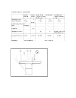
9.6 Adjusting of the cross-ruler
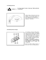
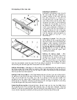
Adjusting of parallelism
Parallelism of lengthwise ruler (A) with
the saw blade (B) gets adjusted by
position change of the ruler carrying
bar with protrusion or insertion of
carrying bars (D) in place where the
ruler is fixed to the cast iron table. After
releasing of screws (C) and releasing
of fixing nuts it is possible to turn with
the distance bar and to screw it in or
out for a new dimension of distance. It
is necessary to fix the new position of
the bar by means of 2 nuts in the edge
of table extension.The ruler is adjusted
from the producer with a divergence to
the saw blade of cca 0,1 ÷ 0,2
mm/1000 mm.
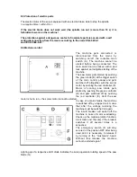
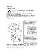
adjusting of plumb:
The cross-ruler
(A) is placed at the supporting frame
(B) and its plumb to the saw blade gets
adjusted - after releasing of arresting
stars (C, D) and of arresting screw (F) -
by turning with the eccentric sprung
plunger (E)
. Do not forget to draw up
the arresting elements again after
adjusting the position.
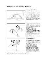
Setting of sawing angle :
After
arresting stars (C and D) have been
released and the centring sprung pin
(E) has been pulled to the lower
position (it will remain in this position
after being turned slightly), the cross
ruler may be adjusted under the angle 0
o
÷45
o
according to scale (G). Do not forget to tighten
the arresting components again after the position has been adjusted.
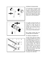
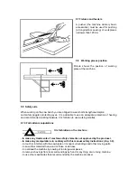
Setting of backstops :
Backstops of cutting width (J) are adjustable after the arresting lever
has been released by being shifted in a groove of the cross ruler profile (A) while the value of
the width is being read on the scale. Do not forget to tighten the arresting components again
after the position has been adjusted.!
Setting of the zero position:
In the perpendicular direction of cross ruler (A) to the saw disc
its position is secured with sprung centring pin (E). If the cutting width set by the backstop
does not correspond to the reality (e.g. due to a change in the saw disc width), the
adjustment may be altered after releasing two arresting screws on the shim in the ruler
profile groove in the place of the sprung centring pin. Do not forget to tighten the arresting
components again after the position has been adjusted.
Supporting frame position:
Supporting frame (B) with cross ruler (A) may be shifted along
the supporting bar of the machine after arresting lever (H) has been released. Securing
callipers (I) prevent supporting frame (B) from falling off the supporting rod. The position of
cross ruler (A) may also be altered by its being moved to the other side of frame (B).
Содержание PF 400 S
Страница 1: ...DIMENSION SAW PF 400 S Service instructions updated 9 2002 ...
Страница 17: ...6 3 Installment of demountable parts ...
Страница 35: ......

