R&S OSP
Instrument Functions
Module Functions
Quick Start Guide 1505.3896.62 - 14
98
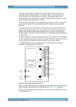
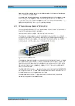
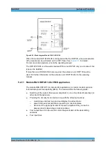
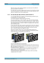
Figure 5-36: Module R&S OSP-B114
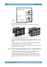
The relay K1 with N-connectors is a DPDT type. When not activated (no voltage
applied to the relay) and after Reset, the terminals 1 - 2 and 3 - 4 are connected.
When activated, the terminals 1 - 3 and 2 -4 are connected.
The SPDT relay (K5) with SMA connectors is controlled by the interlock. With interlock
loop open, a RF connection is provided from the terminal C (Common) to the position
NC (normally closed).
With interlock loop closed, a RF connection is provided between the terminal C
(Common) and the position NO (normally open).
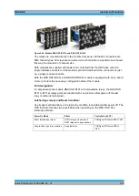
The interlock status is shown by the red LED on the module front panel, too.
Red LED switched on
Interlock loop is open
switched off
Interlock loop is closed
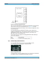
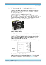
Figure 5-37: Block diagram Module R&S OSP-B114
When the module R&S OSP-B114 is configured within the R&S OSP, a manual
operation of the module can be performed via the OSP Panel. See chapter 3.3.9 for
details.
For remote control operation, for details in the application of this module and for the
connector pin assignments, refer to the operating manual.
Содержание OSP-B011
Страница 132: ......


