R&S OSP
Instrument Functions
Module Functions
Quick Start Guide 1505.3896.62 - 14
93
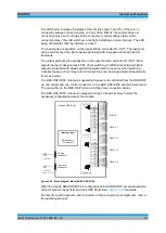
the relay. To maintain a RF connection between the terminal C (Common) and one of
the six output terminals, a continuous voltage is to be applied to the corresponding
power terminal of the relay.
In case of the SPDT relay, a RF connection is provided from the terminal C (Common)
to the position NC (normally closed) with no voltage applied to the relay. To maintain a
RF connection between the terminal C (Common) and the position NO (normally
open), a continuous voltage is to be applied to the relay.
Note that for the SP6T relay only one out of the six terminals is allowed to be activated
at the same time. When operating the OSP-B123/124 inside the OSP, the OSP
firmware takes care for correct switching of the SD6T relay.
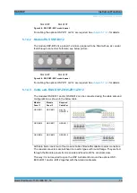
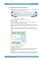
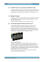
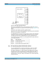
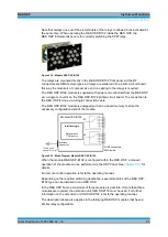
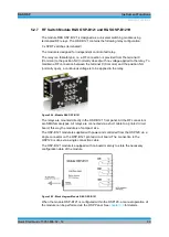
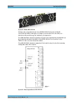
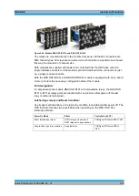
Figure 5-28: Module R&S OSP-B123
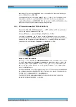
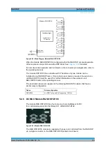
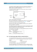
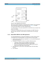
Figure 5-29: Module R&S OSP-B124
All relays are is mounted directly in the OSP-B123/124 front panel. All the RF
connectors are SMA female types. All relays are connected via a short cable to a
printed circuit board; this way the module is of compact size.
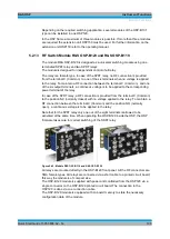
The OSP-B123/124 module is supplied with power and controlled from the OSP120 via
a single connector on the OSP-B123/124 printed circuit board (OSP-B123 has got two
boards). The connection to the OSP120 is done via one (OSP-B123) or two (OSP-
B124) connection cables.
Содержание OSP-B011
Страница 132: ......

