R&S OSP
Preparing for Use
Rear Panel Tour
Quick Start Guide 1505.3896.62 - 14
17
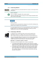
2.4.2 CAN Bus Connector
9-pin connector D-Sub male used to connect the R&S OSP120 or R&S OSP130 to
extension units R&S OSP150. Refer to Instrument Functions in
chapter 5
Maximum input levels
The maximum input levels and voltages of the input connectors at the front and rear
panel must not be exceeded.
Supply Voltage over CAN bus
In some CAN bus applications the R&S OSP120, OSP130 or OSP150 is required to
deliver the supply voltage to an external device. An example for this is the connection
of the fiber-optic extender R&S OSP-Z104. Using the cable OSP-Z106 is
recommended for this case.
However, when connecting an R&S OSP150 to an OSP120 or OSP130, this supply
voltage line must not be present. Using the connecting cables R&S OSP-Z101 or
R&S OSP-Z102 is recommended. Not observing these precautions may damage the
power supplies in the R&S OSP.
See also in the operating manual for the pinout of the CAN bus connector.
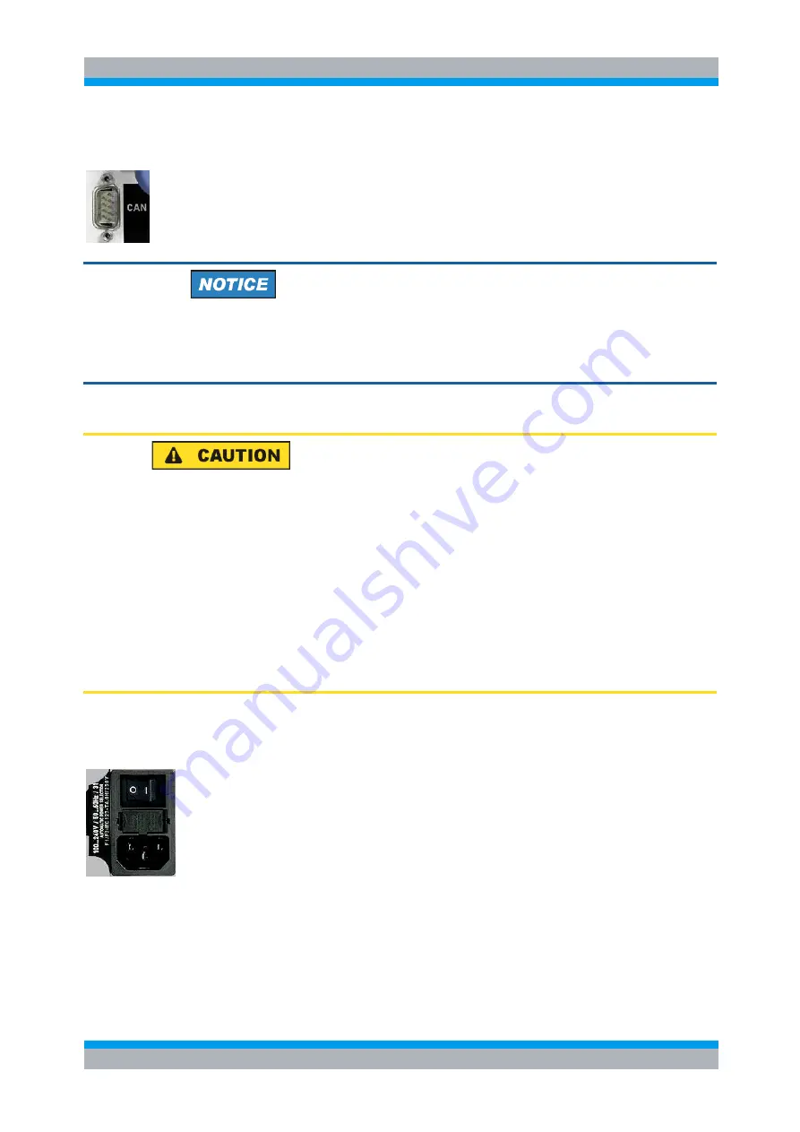
2.4.3 Mains Switch and Connector
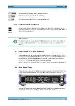
The mains connector is located at the bottom left corner of the rear panel.
Next to the connector is a mains fuse, and above the fuse the mains switch. With the
positions “0” the instrument is disconnected from mains, and in position “1” it is
connected. See
chapters 2.5.6
Содержание OSP-B011
Страница 132: ......

