background image

R&S OSP 

Preparing for Use 


Putting the Instrument into Operation 


Quick Start Guide 1505.3896.62 - 14 

20 

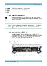
2.5.6  Connecting the Instrument to the AC Supply 

The R&S OSP is automatically adapted to the AC supply voltage supplied. The supply 
voltage must be between 100 V and 240 V with frequencies ranging from 50 Hz to 
60 Hz (see also the tolerances quoted in the "Specifications"). The mains connector is 
located in the lower left corner of the rear panel.  

►  Connect the instrument to the AC power source using the AC power cable 

delivered with the instrument.  

The maximum power consumption of the instrument depends on the installed options. 
The typical power consumption is also listed in the "Specifications".  

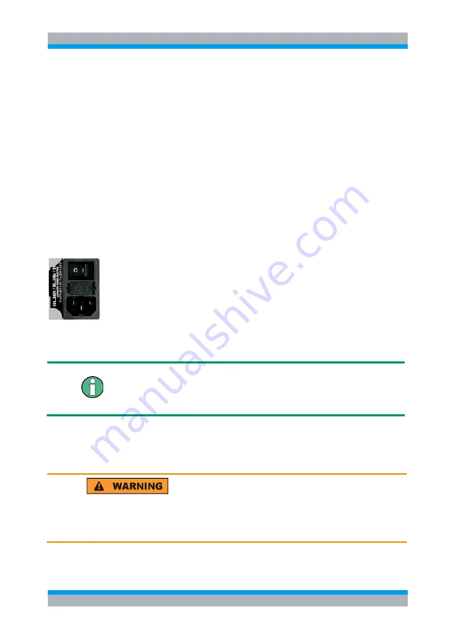
The R&S OSP is protected by two fuses located in the fuse holder below the AC power 
switch; see Replacing Fuses.  

2.5.7  Power on and off 

The mains connector is located at the bottom left corner of the rear panel.  


To turn the power on or off, press the AC power switch to position I (On) or 0 (Off). 

See also Replacing Fuses.  

After power-on, the R&S OSP instrument is in ready state after about 30 seconds.  

The STANDBY key at the front panel of the instrument is used to toggle between 
standby and ready state. The AC power switch can be permanently on.  

Switching off is required only if the instrument must be completely removed from the 
AC power supply but may be used in order to reduce power consumption when not in 
use.  


Extension units


If communication between OSP120 or OSP130 and any extension unit OSP150 
connected via CAN bus cannot be established properly, try to turn on the extension 
unit(s) first before turning on the OSP120 or OSP130. 

2.5.8  Replacing Fuses 

The instrument is protected by two fuses (IEC 127- T4.0H/250V, stock no. 
0020.7600.00) located in the fuse holder below the AC power switch on the rear panel.  


Shock hazard


For fuse replacement, ensure that the instrument is switched off and disconnected 
from the power supply by removing the plug from the AC power connector. 

 
To replace the fuses  

Содержание OSP-B011

Страница 1: ...PAD T M 3574 3259 02 01 00 CI 1 EN R S OSP Open Switch and Control Unit Quick Start Guide Quick Start Guide Test and Measurement 1505 3896 62 14 ...

Страница 2: ...2 Option Module R S OSP B123 stock no 1515 5527 02 Option Module R S OSP B124 stock no 1515 5533 02 Option Module R S OSP B125 stock no 1515 5540 02 Option Module R S OSP B126 stock no 1515 5556 02 Option Module R S OSP B127 stock no 1505 4728 02 Option Module R S OSP B128 stock no 1505 4734 02 Option Module R S OSP B129 stock no 1517 7004 02 Option Module R S OSP B131 stock no 1505 4740 02 Option...

Страница 3: ... Switch and Connector 17 2 5 Putting the Instrument into Operation 18 2 5 1 Unpacking the Instrument and Checking the Shipment 18 2 5 2 Instrument Setup 19 2 5 3 Bench Top Operation 19 2 5 4 Mounting in a 19 Rack 19 2 5 5 EMI Protective Measures 19 2 5 6 Connecting the Instrument to the AC Supply 20 2 5 7 Power on and off 20 2 5 8 Replacing Fuses 20 2 5 9 Standby and Ready State 21 2 6 Maintenance...

Страница 4: ...neral Actions of R S OSP Panel 40 3 3 5 Addressing R S OSP Modules 41 3 3 6 Controlling the R S OSP B101 B106 B107 B111 B127 B132 42 3 3 7 Controlling the R S OSP B102 B112 B128 43 3 3 8 Controlling the R S OSP B103 B158 45 3 3 9 Controlling the R S OSP B104 B114 47 3 3 10 Controlling the R S OSP B108 51 3 3 11 Controlling the R S OSP B131 52 3 3 12 Controlling the R S OSP B116 B136 52 3 3 13 Cont...

Страница 5: ...tch Module R S OSP B102 B112 B128 82 5 2 3 I O Module R S OSP B103 84 5 2 4 I O Module R S OSP B104 85 5 2 5 RF Switch Module R S OSP B106 B132 88 5 2 6 DC MUX Module R S OSP B108 89 5 2 7 RF Switch Module R S OSP B121 and R S OSP B121H 90 5 2 8 RF Switch Modules R S OSP B122 OSP B122H and OSP B133 91 5 2 9 RF Switch Module R S OSP B123 and R S OSP B124 92 5 2 10 RF Switch Module R S OSP B125 and ...

Страница 6: ...the R S OSP B104 118 5 3 8 Using the R S OSP B121 120 5 3 9 Using the R S OSP B122 OSP B122H and OSP B133 120 5 3 10 Using the R S OSP B123 to R S OSP B126 and R S OSP B129 121 5 3 11 Path Configuration 122 5 4 R S OSP Switch Cycle Counter 126 5 5 R S OSP Selftest 128 5 5 1 Selftest via R S OSP Panel 128 5 6 R S OSP Configuration Check 128 5 6 1 System Info via R S OSP Panel 128 5 7 SCPI Read Writ...

Страница 7: ...e R S OSP B128 84 Figure 5 17 Module R S OSP B103 84 Figure 5 18 Block Diagram Module R S OSP B103 85 Figure 5 19 Module R S OSP B104 86 Figure 5 20 Block Diagram Module R S OSP B104 87 Figure 5 21 Module R S OSP B106 88 Figure 5 22 Block Diagram Module R S OSP B106 89 Figure 5 23 Module R S OSP B108 89 Figure 5 24 Module R S OSP B121 90 Figure 5 25 Block diagram Module R S OSP B121 90 Figure 5 26...

Страница 8: ...dule R S OSP B116 103 Figure 5 45 Module R S OSP B116 and R S OSP B136 103 Figure 5 46 Module R S OSP B101L and R S OSP B102L 104 Figure 5 47 Module R S OSP B158 105 Figure 5 48 Block Diagram Module R S OSP B158 106 Figure 5 49 Module R S OSP B142 variant 03 with 3 DP3T switches 107 ...

Страница 9: ...R S OSP B111 stock no 1505 4605 02 Option Module R S OSP B111UL stock no 1528 1531 13 16 Option Module R S OSP B111VL stock no 1515 5991 13 16 Option Module R S OSP B112 stock no 1505 4611 02 Option Module R S OSP B114 stock no 1505 4711 02 Option Module R S OSP B116 stock no 1515 5827 02 Option Module R S OSP B119 stock no 1515 5856 02 Option Module R S OSP B121 stock no 1515 5504 02 Option Modul...

Страница 10: ...umentation Overview Quick Start Guide 1505 3896 62 14 10 Option Module R S OSP B136 stock no 1522 4500 02 Option Module R S OSP B142 stock no 1528 1048 03 11 12 13 Option Module R S OSP B158 stock no 4094 7300 02 ...

Страница 11: ...structions at the beginning of this manual 2 1 Front Panel Tour R S OSP120 This chapter gives an overview of the front panel controls and connectors of the R S OSP120 and gives all information that is necessary to put the instrument into operation and connect external devices Notes on reinstallation of the instrument software appear at the end of the chapter Chapter 3 3 R S OSP Panel Functions of ...

Страница 12: ...a CAN bus On an R S OSP150 the logic is inverted the CLK indicator goes off shortly during CAN bus activity The STANDBY key serves the following purpose Toggle between standby and ready state indicated by the yellow and green PWR LED respectively 2 1 2 Front Panel Connectors 2 1 2 1 USB Connectors Single Universal Serial Bus connectors of type A master USB used to connect a keyboard or flash drive...

Страница 13: ...tings are not required It is recommended to use a double shielded monitor cable equipped with ferrites at each end 2 2 Front Panel Tour R S OSP130 This chapter gives an overview of the front panel controls and connectors of the R S OSP130 and gives all information that is necessary to put the instrument into operation and connect external devices Notes on reinstallation of the instrument software ...

Страница 14: ...n in chapter 5 3 In the top row next to the screen there are three keys to quickly access different hierarchy levels in the menus pressing the key FUNCTION executes a switching action if applicable pressing the key OK confirms a selection for example for going to the next menu level pressing the key STATUS displays status information for the chosen item device or module or changes the selection of...

Страница 15: ...ecommended to use double shielded USB cables 2 3 Front Panel Tour R S OSP150 This chapter gives an overview of the front panel controls of the R S OSP150 The front panel of the R S OSP150 is similar to the front panel of the R S OSP120 having the Standby key and the three status LEDs but does not have any connector See chapter 2 1 1 for the description of the front panel elements Please notice tha...

Страница 16: ...02 Relay module consisting of two coaxial relays of SP6T type the RF coaxial connectors are SMA type Option R S OSP B103 I O module with 16 Bit input output ports the connectors are D Sub types 25 pin female for output and male for input In case of the options which can be installed in the R S OSP the connectors related to each option are described in detail in the operating manual 2 4 1 LAN Conne...

Страница 17: ...connection of the fiber optic extender R S OSP Z104 Using the cable OSP Z106 is recommended for this case However when connecting an R S OSP150 to an OSP120 or OSP130 this supply voltage line must not be present Using the connecting cables R S OSP Z101 or R S OSP Z102 is recommended Not observing these precautions may damage the power supplies in the R S OSP See also in the operating manual for th...

Страница 18: ...ng the Instrument and Checking the Shipment Remove the instrument from its packaging and check the equipment for completeness using the delivery note and the accessory lists for the various items First pull off the polyethylene protection pads from the instrument s rear feet and then carefully remove the pads from the instrument handles at the front Pull off the corrugated cardboard cover that pro...

Страница 19: ...at least 10 cm 2 5 3 Bench Top Operation If the R S OSP is operated on a bench top the surface should be flat The instrument is used in horizontal position standing on its feet 2 5 4 Mounting in a 19 Rack The instrument can be mounted in 19 racks using a ZZA 211 adapter order number 1096 3260 00 Please note the mounting instructions supplied with the rack adapter Allow for sufficient air supply in...

Страница 20: ...rear panel To turn the power on or off press the AC power switch to position I On or 0 Off See also Replacing Fuses After power on the R S OSP instrument is in ready state after about 30 seconds The STANDBY key at the front panel of the instrument is used to toggle between standby and ready state The AC power switch can be permanently on Switching off is required only if the instrument must be com...

Страница 21: ...when changing from Standby to Ready state the left PWR LED is immediately switched to green and all modules are power supplied Please note that the Linux operating system of R S OSP takes about 30 seconds to start up After this time the R S OSP is ready for operation Shock hazard The instrument is still power supplied while it is in standby mode 2 6 Maintenance The R S OSP does not require any spe...

Страница 22: ...Cable In addition the R S OSP120 provides interfaces for monitor connection and USB connection An external monitor shows the menus of the Linux Operating System if any access or setup within the Linux Operating System should be necessary A keyboard simplifies the entry of data see Connecting a Keyboard A flash drive supports the firmware update see Connecting a USB Flash Drive 2 7 1 Connecting a U...

Страница 23: ...panel of the R S OSP120 or OSP130 To establish a LAN connection proceed as follows Refer to chapter Assigning an IP Address and learn how to avoid connection errors Connect an appropriate LAN cable to the LAN port Use a commercial RJ 45 cable to establish a non dedicated network connection or a cross over RJ 45 cable to establish a dedicated connection between the instrument and a single PC Dedica...

Страница 24: ...d as follows Press the STANDBY key which will shut down the Linux operating system and set the instrument to standby state If desired set the AC power switch to position 0 Off Standby state It is recommended to switch the R S OSP to standby state before disconnecting it from the AC supply 2 9 Remote Operation in a LAN A LAN connection is used to integrate the R S OSP not the OSP150 into a home com...

Страница 25: ...sical connection to the LAN without any previous R S OSP configuration Priority 1 A user defined static IP address This address can be defined but must not in addition to the default address See chapter 3 3 3 for information how to configure the user defined IP address via the OSP Panel application Priority 2 A static default IP address Per default the R S OSP is set to the IP address 192 168 48 1...

Страница 26: ...on or the ENTER key on the keyboard OK key for the R S OSP130 for confirmation and to continue the operation Manual TCP IP configuration If your network does not support DHCP proceed as follows 1 Connect the R S OSP120 or OSP130 via a cross over RJ 45 cable to your computer or network not supporting DHCP 2 Set the network configuration of your computer to work with a static IP address The followin...

Страница 27: ...ll access to all R S OSP functions To start the OSP Panel connection 4 Connect the R S OSP to a LAN and determine its IP address see Remote Operation in a LAN It is necessary to have a VISA library installed on your computer 5 Install the OSP Panel application on your computer connected to the LAN The VISA libraries which are necessary for running the OSP Panel are available on a separate disc NI ...

Страница 28: ...onitor and keyboard to the R S OSP120 and switch on the instrument The messages of the Linux boot process are displayed on the monitor Wait until the boot process is finished takes about 30 seconds and press the ENTER key 9 R S OSP130 Connect the external keyboard to the R S OSP120 and switch on the instrument Wait until booting is complete Change from regular display to Linux system login by pres...

Страница 29: ...ifications are provided on the Internet at the download site of the R S OSP homepage The installation of a new firmware version is performed via the USB interface A de installation of the old firmware is not necessary The firmware update is performed while the instrument is running The new firmware will be loaded right after the update process To perform a firmware update perform the following ste...

Страница 30: ...for details Firmware Update The firmware update is not allowed to be performed running the GUI via Web Browser and VNC Doing this will abort the firmware installation procedure 2 12 Read the actual the Firmware Version The currently installed firmware version of the different R S OSP units can be read in several ways as described in the following chapters 2 12 1 Get Firmware Version using R S OSP ...

Страница 31: ...d button see below example The last part of the string shows the actual firmware version 1 5 for the above example With Firmware version 2 51 onwards the actual version of the OSP is read out in the configuration string too See below example for OSP120 with Ser No 100008 and Var 02 Rohde Schwarz OSP120 100008 Var02 2 51 With Firmware version 2 57 onwards the firmware version of the OSP is read out...

Страница 32: ...a front display and panel keypad GUI Figure 3 2 Chapter 4 and Chapter 5 3 1 R S OSP120 and R S OSP130 via Ethernet connection between OSP and laptop PC Web GUI via VNC or OSP Panel Figure 3 3 Chapters 3 1 3 7 1 5 3 1 Web GUI 3 2 to 3 3 OSP Panel Since the R S OSP120 only has remote control capability the manual operation of the instrument is achieved either via a connected keyboard mouse and monit...

Страница 33: ...n the following we assume that you are familiar with standard Windows dialogs and mouse operation 3 1 Connecting R S OSP and PC Please read chapter 2 9 1 for understanding the possibilities of IP address assignments The following setup describes the connection of the R S OSP120 or R S OSP130 within a dedicated network i e the connection to a single computer in case you are not using the dynamic TC...

Страница 34: ... install the application proceed as follows Insert the documentation CD on the disk drive of your computer Select the directory OSP Panel on the CD select the file setup exe and press the ENTER button to start the installation If the installation is complete confirm and exit the installation program 3 3 R S OSP Panel Functions The following sections can help you to make efficient use of the OSP Pa...

Страница 35: ...ion mode and the following dialog appears The R S OSP remains in simulation mode as long as no connection to an instrument via LAN is performed To connect an R S OSP via LAN perform the following steps 14 Get the actual IP address as described in chapter 3 1 and enter the address in the input field RESOURCE DESCR 15 Press the Connect to device button at the upper right corner of the OSP Panel dial...

Страница 36: ... field together with the installed options Note that it is necessary to register the R S OSP once if the instrument is switched on for the first time or if the configuration has changed or if a firmware update has been made See chapter 3 3 3 for further information See also in the operating manual for actions related to extensions with an OSP150 In the below example an R S OSP130 Device is found o...

Страница 37: ...ersion xxxx xxxxK03 Serial Number 100001 The above example results in R S OSP address 3100001 OSP Description Base unit OSP120 OSP130 or Extension unit OSP150 Mainboard Serial Number The serial number read back from the R S OSP Mainboard is displayed Mainboard Part Number The part number read back from the R S OSP Mainboard is displayed Mainboard Hardware Code The hardware code read back from the ...

Страница 38: ...f the OSP version last digit of the OSP part number and the OSP serial number 6 digit number The information of the OSP version and the serial number can be found on the serial number label above the mains switch on the OSP s rear side Use the drop down list to set the device number to F01 Version OSP120 xxxx xxxxK02 Serial Number 100001 The above example results in OSP address 2100001 21 Pressing...

Страница 39: ...r 2 9 1 1 for more information on the LAN configuration mode Select the menu function Configure TCPIP and the following dialog is opened The upper half of the dialog shows the last used DHCP address and the actual static IP address A new user defined static IP address can be entered together with a subnet mask Changing of IP address Whenever the IP address is changed via the OSP Panel and the prev...

Страница 40: ...ons which can be done from the OSP Panel With the menu function Configure Reset all switches in the connected R S OSP are set to their default positions The functions Configure Select all Switches and Configure Deselect all Switches define the starting point when collecting the settings for a path configuration See chapter 3 4 for more details The menu function Utility Re Initialize Frames and Mod...

Страница 41: ...upper right field of the OSP Panel dialog By double clicking the required R S OSP module a window is opened which shows all the setup functions available for the selected module The title line of that window also indicates the slot where this module is placed or both slots if the module has double width see also chapter 5 1 2 See the following chapters for the dialogs of the different R S OSP modu...

Страница 42: ...losed position When the relay is not activated terminal NC is connected to terminal C The terminal NO is the Normally Open position If the relay is activated the terminal NO is connected to terminal C The buttons K11 up to K16 are not required for manual operation of the switches but for defining a path configuration K12 Any button K11 up to K16 in grey color indicates that this relay is not selec...

Страница 43: ...ation It will apply to the following modules Option Relay configuration OSP B106 3 x SPDT relay with N connectors 12 GHz 3 x SPDT relays with BNC connectors 900 MHz 2 A OSP B107 6 x SPDT relay solid state 6 GHz OSP B111 6 x SPDT relay 40 GHz OSP B111UL 3 or 6 x SPDT relay 50 GHz OSP B111VL 3 or 6 x SPDT relay 67 GHz OSP B127 6 x SPDT relay solid state terminated 10 GHz OSP B132 6 x SPDT relay with...

Страница 44: ...operation of the switches but for defining a path configuration see chapter 3 4 K1 A button K1 and or K2 in grey color indicates that this relay is not selected A non selected relay is not considered when defining a path configuration K2 To take over particular relays into the path configuration the relay buttons must be selected by clicking on each of the relay buttons required The selected relay...

Страница 45: ... got the same relay configuration It will apply to the following modules Option Relay configuration OSP B112 2 x SP6T relay 40 GHz OSP B128 Up 3 x SP6T relay solid state terminated 10 GHz OSP B122H 1x SP6T relay terminated 40 GHz OSP B133 1x SP6T relay N connectors 12 4 GHz 3 3 8 Controlling the R S OSP B103 B158 After selection of the R S OSP B103 or the R S OSP B158 module the following dialog i...

Страница 46: ...outputs to the defined output pattern 29 The actual setting of the R S OSP B103 outputs now is displayed in the output pattern field Ch1 to Ch16 30 The hexadecimal representation of the output pattern is displayed in the OSP B103 dialog too Ch1 corresponds to the lowest bit having the value 1 whereas Ch16 is the highest bit having the value 8000 OSP B103 dialog When the dialog for operation of the...

Страница 47: ... user is prompted to close the actual panel and to open it again After opening the OSP B158 panel again a special interface for controlling the AU600 antenna system appears Figure 3 4 AU600 panel design AU600 panel design The special AU600 panel design is explained in detail in the R S AU600 manual 3 3 9 Controlling the R S OSP B104 B114 After selection of the R S OSP B104 module the following dia...

Страница 48: ...made between connectors 1 and 4 and between 2 and 3 The buttons R1 up to R4 are not required for manual operation of the switches but for defining a path configuration see chapter 3 4 R1 Any button R1 up to R4 in grey color indicates that this relay is not selected A non selected relay is not considered when defining a path configuration R2 To take over particular relays into the path configuratio...

Страница 49: ...nce to the relay data specification If the delay time is too short the relay status also may be shown as faulty See chapter 5 2 4 for further information on the relay delay time 3 3 9 2 Setting the Output Pattern Clicking on one of the channel buttons in the output pattern field the status of the output channel can be changed An output channel marked in blue color indicates that the output channel...

Страница 50: ...isplayed in the input pattern field Ch1 to Ch4 The hexadecimal representation of the input pattern is displayed in the OSP B104 dialog too Ch1 corresponds to the lowest bit having the value 1 whereas Ch4 is the highest bit having the value 8 35 An input channel marked in blue color indicates that the input channel reads high level 36 An input channel marked in white color indicates that the input ...

Страница 51: ...manual operation of the switches but for defining a path configuration see chapter 3 4 K1 A button K1 and or K2 in grey color indicates that this relay is not selected A non selected relay is not considered when defining a path configuration K1 To take over particular relays into the path configuration the relay buttons must be selected by clicking on each of the relay buttons required The selecte...

Страница 52: ...apter 3 4 K12 Any button K11 and or K12 in grey color indicates that this relay is not selected A non selected relay is not considered when defining a path configuration K11 To take over particular relays into the path configuration the relay buttons must be selected by clicking on each of the relay buttons required The selected relay is displayed with a button in green color All relays whose rela...

Страница 53: ...onfiguration see chapter 3 4 K12 Any button K11 and or K12 in grey color indicates that this relay is not selected A non selected relay is not considered when defining a path configuration K11 To take over particular relays into the path configuration the relay buttons must be selected by clicking on each of the relay buttons required The selected relay is displayed with a button in green color Al...

Страница 54: ...quired relay buttons The selected relay is displayed with a button in green color All relays whose relay buttons are selected are taken over into a path configuration Pressing the Shift key while clicking on a relay button will toggle between selecting all relays of this module and deselecting all of them 3 4 Path Configuration A very comfortable way to define the different switching paths require...

Страница 55: ...ather large use Configure Select all Switches instead Don t forget to select deselect all switches which are not correctly selected by this default selection 3 4 1 Save a Path The path configuration is supported by the OSP Panel application Refer to chapters 3 2 and 3 3 for the installation and operation of the OSP Panel To have a defined condition for the path switching it is recommended to start...

Страница 56: ...he path name is limited to a maximum of 49 characters OSP Panel does not allow to enter a longer name 38 Pressing the button Save saves the path in the flash memory of the R S OSP The upper data field shows the existing paths which already are stored in the R S OSP flash memory 3 Takes over the actual switching into the path and stores the path in the R S OSP Invalid path configurations When chang...

Страница 57: ...s follows 39 Start the OSP Panel 40 Select Path Switch Path in the OSP Panel The following dialog appears The left field shows the names of all path configurations which already have been defined The highlighted path configuration will be switched when pressing the Switch button The right field Path Definition shows all relays and settings related to the selected path The selected path configurati...

Страница 58: ...path will be deleted from the flash memory in the R S OSP The only possibility to recover a path which was unintentionally deleted is to use the Import Path function assuming the path has been exported before Pressing this button will exit the dialog 3 4 4 Export a Path If a path has been defined as described in the previous chapter the path can be exported to a file as follows 43 Start the OSP Pa...

Страница 59: ...which paths are currently selected in this dialog Clicking into a line toggles selection and deselection of the path By activating the check box below the list all paths can be selected or deselected at once End of path selection go to the following dialog Pressing this button will exit the dialog In the next dialog the directory is chosen where the files containing the path information are create...

Страница 60: ...he dialog has no meaning Only the directory name in the field at the top of the dialog is used The selected paths will be saved as files with the suffix txt to the directory indicated Pressing this button will exit the dialog 3 4 5 Import a Path If a path has been exported as described in the previous chapter the path can be imported again It is required that the OSP Panel is connected to an instr...

Страница 61: ...and this one and using the Ctrl key at the same time will add the second file as a marked one Will exit the dialog The selected files will be imported and stored as paths to the R S OSP flash memory The marked file will be removed from the list of selected files All files will be removed from the list of selected files 3 5 Sample Session The sample session shows a typical application of the R S OS...

Страница 62: ... To obtain the correct switching for a new path configuration it is recommended to reset the R S OSP Select in the OSP Panel Configure Deselect all Switches According to the above example for amplifier PA1 the following paths are required Signal path Required relay position Sig Gen to PA1 input R S OSP B101 K11 NO PA1 Fwd to Power Meter Ch A R S OSP B102 K1 1 PA1 Fwd to Power Meter Ch B R S OSP B1...

Страница 63: ...A2 the following paths are required Signal path Required relay position Sig Gen to PA2 input R S OSP B101 K11 NC K12 NO PA2 Fwd to Power Meter Ch A R S OSP B102 K1 2 PA2 Fwd to Power Meter Ch B R S OSP B102 K2 2 Start the OSP Panel and make sure not to take over any undesired relay setting Select therefore in the OSP Panel Configure Deselect all Switches After that select the OSP B101 dialog and s...

Страница 64: ...K12 NC PA3 Fwd to Power Meter Ch A R S OSP B102 K1 3 PA3 Fwd to Power Meter Ch B R S OSP B102 K2 3 Start the OSP Panel and make sure not to take over any undesired relay setting Select therefore in the OSP Panel Configure Deselect all Switches After that select the OSP B101 dialog and set K11 to position NC and K12 to position NC Do not forget to select the K11 and K12 buttons Now select the OSP B...

Страница 65: ...o set up the path for power amplifier PA 1 PA2 and PA3 respectively only a simple step is required Select Path Switch Path in the OSP Panel The following dialog appears Select the path name Path_PA1 press the button Switch and all necessary switching for PA1 is done For PA2 and PA3 proceed accordingly The field Path Definition shows the relay setting of the selected path The path definition also i...

Страница 66: ...on does not need to know the R S OSP hardware configuration If the hardware configuration has to be changed only the path configuration inside the R S OSP must be adapted The external application does not need to be changed For the above examples the following strings are to be sent to the R S OSP ROUTe CLOSe Path_PA1 ROUTe CLOSe Path_PA2 ROUTe CLOSe Path_PA3 Further information on remote control ...

Страница 67: ...t the OSP Panel application select Utility Virtual Mode as shown below Note Alternatively right click the OSP configuration structure in the left field OSP panel and Virtual Mode No instrument must be connected to run OSP Panel in virtual mode off line A selection box pops up for setting up the Simulated Module Configuration Per default OSP frame F01 is offered which can either be model R S OSP120...

Страница 68: ...ts as requested For any additional R S OSP150 proceed accordingly After completing the configuration press and Then the OSP Panel shows the requested module configuration only as shown in the following example menu 3 6 2 Path Configuration You can now configure the path as usual see chapter 3 4 with the exception that a path can only be exported Exporting is shown in the example below ...

Страница 69: ...l mode 3 7 GUI Info Line With OSP Panel version 2 57 onwards you can activate an info line which is shown at the R S OSP130 built in display connected monitor and Web GUI For details on your firmware version see the related Release Notes or Configure the info line either via the OSP Panel application or via SCPI SYSTem OPTion commands refer to the operating manual You can only configure the info l...

Страница 70: ...nu allows to select the following modes Info Line Mode R S OSP130 display OFF No info line is shown Customer Text You can define any text to be shown Actual Path Shows the name of the currently switched path To enter a text line with a maximum of 49 characters select the Info Line Mode Customer Text After pressing the button you are prompted to press the STATUS key on R S OSP130 front panel for ac...

Страница 71: ...keyboard and monitor or VNC When powering OFF ON the R S OSP130 the GUI info line remains active but In case of text info the text is set to the default content no customer defined info text In case of path info the display may show no pre defined path if the current path has become invalid The same happens after any manual switching The following screenshots show the GUI display with the custom t...

Страница 72: ...of the Modules Manual operation of the instrument functions is achieved by the OSP Panel or using the graphical user interface GUI of the R S OSP via Web Browser all models of the R S OSP family The model R S OSP130 can be operated using the GUI together with a display and keyboard The application OSP Panel runs on an external computer with Windows Operating System The external computer is connect...

Страница 73: ...tely be controlled via LAN interface The R S OSP120 contains no front elements for manual operation and is therefore only to be used in remote operation The R S OSP130 can operate as a stand alone instrument thus not requiring remote control Front panel keys and a display allow local operation It may also be integrated in remotely controlled systems The R S OSP150 is an extension of the OSP120 or ...

Страница 74: ... take the R S OSP modules The single board computer is plugged onto the R S OSP Main Board The basic component on the mainboard is an FPGA which supplies all necessary interfaces between computer PCI Bus and R S OSP internal interfaces like the control ports for the R S OSP modules The CAN bus which is used to connect further R S OSP extension units is implemented in the FPGA as well The power is ...

Страница 75: ...the R S OSP130 Figure 5 2 Block Diagram R S OSP130 Additional to the OSP120 in the OSP130 the connection to the front side display unit and keys is available for local operation No connection to an external monitor is available Finally the block diagram of the OSP150 extension unit shows its main functional blocks Figure 5 3 Block Diagram R S OSP150 ...

Страница 76: ... are designated with A11 A12 and A13 The same order is used when addressing the modules i e R S OSP module 1 corresponds to slot A11 etc In principle the R S OSP modules can be installed in the slots in any order A slot which is not occupied will be shown as empty by the OSP Panel application Module Slots The depth of the module slot A11 is limited Only modules with a depth 70 mm like the modules ...

Страница 77: ...view it corresponds to slot A12 connected via cable W6 see figure below Figure 5 6 Block Diagram R S OSP120 Var 12 Configuration of 2 slot modules OSP modules with 2 slot size and requiring two interface cables W6 and W7 like the modules OSP B105 B115 B125 B126 only can be mounted in A12 A13 or A12F A13F That means with a 2 slot module configured in A12 A13 and one module configured in the OSP fro...

Страница 78: ...limited for a maximum offset of one module only That means if one Module Panel is mounted in the slot A13F at the OSP front side a second Module Panel for example can be installed at the OSP rearside in any one of the three available slots offset 1 slot But it is not possible to mount one Module Panel in the slot A12F at the OSP front side and a second Module Panel at the OSP rearside in slot A11 ...

Страница 79: ...pter 5 1 4 3 for details 5 1 4 3 Cable sets R S OSP Z010 Z011 Z012 The modules OSP B011 and or OSP B012 can be connected using the cable sets and configurations as shown in the below table Module Panel 1 Module Panel 2 Required Cable Set OSP B011 OSP B011 max 3 x OSP Z010 OSP B012 OSP B011 OSP Z011 OSP B012 OSP B012 OSP Z012 All Cable Sets consist out of four coaxial cables fitted with suitable co...

Страница 80: ...e installed from OSP front side always is mounted in slot A13F From interface point of view it corresponds to slot A13 connected via cable W7 see figure below The second module installed from OSP front side is mounted in slot A12F From interface point of view it corresponds to slot A12 connected via cable W6 see figure below Figure 5 11 Block Diagram R S OSP150 Var 15 Configuration of 2 slot modul...

Страница 81: ...ts of six SPDT switches All six switches can be operated independently from each other The relay is a failsafe type i e an RF connection is provided from the terminal C Common to the position NC normally closed with no voltage applied to the relay To maintain an RF connection between the terminal C Common and the position NO normally open a continuous voltage is to be applied to the relay Figure 5...

Страница 82: ...es are required the extension unit R S OSP150 must be used For further information on the extension unit R S OSP150 refer to the operating manual The description above also applies to the following R S OSP modules that have a similar relay configuration Option Relay configuration OSP B107 6 x SPDT relay solid state 6 GHz OSP B111 6 x SPDT relay 40 GHz OSP B127 6 x SPDT relay solid state terminated...

Страница 83: ...OSP B102 module is equipped with an on board memory to store the necessary configuration data of the module 1 6 C 1 6 C 2 3 4 5 2 3 4 5 Module OSP B102 Interface logic Relay drivers I2C memory K1 K2 All RF connectors SMA female Interface connector To OSP frame cable W5 or 6 or 7 Figure 5 15 Block Diagram Module R S OSP B102 When the module R S OSP B102 is configured within the R S OSP a manual ope...

Страница 84: ...must be configured starting from position K1 onwards In the above picture two relays are fitted the openings for K3 are covered by a sheet metal strip 5 2 3 I O Module R S OSP B103 The module R S OSP B103 is a digital I O module consisting of a 16 bit input and a 16 bit output port The input ports are available on the upper D Sub connector The input port can be read at any time Each input is prote...

Страница 85: ...Ch1 Ch2 Ch15 Ch16 Ch7 Ch14 28 V GND Ch12 Ch11 Figure 5 18 Block Diagram Module R S OSP B103 When the module R S OSP B103 is configured within the R S OSP a manual operation of the module can be performed via the OSP Panel See chapter 3 3 9 for details For remote control operation and for details on the connector pin assignments refer to the operating manual Depending on the required application se...

Страница 86: ...ition This line is read from the module and used to display and verify the current status Delay time for Transfer switch The transfer relays may have a settling time which cannot be neglected Per default a delay time of 100 msec is set up for the OSP B104 module The delay time allows the relay to reach it s final position before the new position is read back Refer to the operating manual for furth...

Страница 87: ...OSP via one supply and one control connector on the R S OSP B104 printed circuit board The connection to the R S OSP is done via those two connection cables The R S OSP B104 module is equipped with an on board memory to store the necessary configuration data of the module Interface logic Relay drivers I2C memory Interface connector Output Port Ch6 To OSP frame cable W 5 or 6 or 7 Ch3 Ch4 Ch5 Ch8 C...

Страница 88: ...ion is provided from the terminal C Common to the position NC normally closed with no voltage applied to the relay To maintain an RF connection between the terminal C Common and the position NO normally open a continuous voltage is to be applied to the relay Figure 5 21 Module R S OSP B106 The relays are mounted directly in the R S OSP B106 front panel Three of the relays K1 to K3 have N type conn...

Страница 89: ... OSP B106 has a double width Therefore only one module can be installed in one R S OSP frame If more than one module is required the extension unit R S OSP150 must be used For further information on the extension unit R S OSP150 refer to the operating manual The description above also applies to the following R S OSP modules that have a similar relay configuration Option Relay configuration OSP B1...

Страница 90: ...ormally open a continuous voltage is to be applied to the relay Figure 5 24 Module R S OSP B121 The relays are mounted directly in the OSP B121 front panel All the RF connectors are SMA female types All relays are connected via a short cable to a printed circuit board this way the module is of compact size The OSP B121 module is supplied with power and controlled from the OSP120 via a single conne...

Страница 91: ... as a universal switching module using terminated RF relays The OSP B122 contains the following relay configuration 1 x SP6T switch terminated SMA connectors maximum frequency 18 GHz The relay is a failsafe type i e no RF connection is provided from the terminal C Common to one of the six terminals when no voltage is applied to the relay To maintain a RF connection between the terminal C Common an...

Страница 92: ...les is possible If more than three modules are required the extension unit OSP150 must be used For further information on the extension unit OSP150 refer to the operating manual The description above also applies to the following R S OSP options modules that have a similar relay configuration Option Relay configuration OSP B122H 1 x SP6T relay with SMA 2 9 Connectors 40 GHz terminated OSP B133 1 x...

Страница 93: ...lay Note that for the SP6T relay only one out of the six terminals is allowed to be activated at the same time When operating the OSP B123 124 inside the OSP the OSP firmware takes care for correct switching of the SD6T relay Figure 5 28 Module R S OSP B123 Figure 5 29 Module R S OSP B124 All relays are is mounted directly in the OSP B123 124 front panel All the RF connectors are SMA female types ...

Страница 94: ...unctions Module Functions Quick Start Guide 1505 3896 62 14 94 The OSP B123 124 module is equipped with on board memory to store the necessary configuration data of the module Figure 5 30 Block diagram Module R S OSP B123 ...

Страница 95: ... OSP B125 OSP B125 6 x SPDT switches terminated 3 x SP6T switch terminated 3 x SP6T switch terminated The module is designed for independent control of all relay The relay is a failsafe type In case of the SP6T relay no RF connection is provided from the terminal C Common to one of the six terminals when no voltage is applied to the relay To maintain a RF connection between the terminal C Common a...

Страница 96: ...ted via a short cable to a printed circuit board this way the module is of compact size The OSP B125 126 module is supplied with power and controlled from the OSP120 via two printed circuit boards mounted on the OSP B125 126 The connection to the OSP120 is done via a two connection cables The OSP B125 126 module is equipped with on board memory to store the necessary configuration data of the modu...

Страница 97: ...unit OSP150 refer to the operating manual 5 2 11 Module R S OSP B114 for EMS application The module R S OSP B114 is intended for applications in small or medium systems for Electromagnetic Susceptibility EMS The module fulfills the following tasks Switching of the output of two power amplifiers to one or two transmit antennas or other kind of transducers Providing the circuitry for an interlock lo...

Страница 98: ... Common to the position NC normally closed With interlock loop closed a RF connection is provided between the terminal C Common and the position NO normally open The interlock status is shown by the red LED on the module front panel too Red LED switched on Interlock loop is open switched off Interlock loop is closed Figure 5 37 Block diagram Module R S OSP B114 When the module R S OSP B114 is conf...

Страница 99: ... the relay Figure 5 38 Module R S OSP B131 The relays are mounted directly in the OSP B131 front panel All the RF connectors are N female types All relays are connected via a short cable to a printed circuit board this way the module is of compact size The OSP B131 module is supplied with power and controlled from the OSP120 via a single interface connector on the OSP B131 printed circuit board Th...

Страница 100: ...is to be applied to the corresponding power terminal of the relay In case of the SPDT relay a RF connection is provided from the terminal C Common to the position NC normally closed with no voltage applied to the relay To maintain a RF connection between the terminal C Common and the position NO normally open a continuous voltage is to be applied to the relay Note that for the SP8T relay only one ...

Страница 101: ...nfiguration Option Relay configuration OSP B119 1 x SP8T relay non terminated 2 x SPDT relay non terminated 5 2 14 Power Sensor Module R S OSP PM I The module R S OSP PM I allows to integrate a Power Sensor within the R S OSP The module R S OSP PM I includes one N type feed through connector and one USB Adapter both mounted in the modules front panel The module needs to be completed with a Power S...

Страница 102: ... R S OSP B136 The module R S OSP B116 and B136 are designed as a universal switching modules using two transfer switches DPDT The modules are designed for independent control of both relays The module R S OSP B116 is configured with two transfer relays and SMA connector type the R S OSP B136 with two transfer relays and N connector type When not activated no voltage applied to the relay and after ...

Страница 103: ...Panel See chapter 3 3 9 for details For remote control operation for details in the application of this module and for the connector pin assignments refer to the operating manual The R S OSP B116 136 is a one slot module Within one OSP base unit up to three modules of this type can be installed 5 2 16 RF Switch Module R S OSP B101L B111xL and R S OSP B102L The modules R S OSP B101L R S OSP B111UL ...

Страница 104: ... R S OSP B102L module is equipped with an on board memory to store the necessary configuration data of the module Port designation In comparison to the module R S OSP B101 with monostable relays the R S OSP B101L B111xL relays ports are labelled with 1 and 2 since after power off the last relay condition is maintained Latched type relays and Reset Condition As already mentioned above the last rela...

Страница 105: ...re POWerup RESet Refer to the operating manual for further information on the CONFigure commands 5 2 17 I O and supply Module R S OSP B158 The module R S OSP B158 is designed as a power supply and control module It consists of a 16 bit input a 16 bit differential RS422 output and a power supply connector All ports are D Sub connectors male for input female for output and power supply On the left s...

Страница 106: ...anual 5 2 18 RF Switch Module R S OSP B142 The module R S OSP B142 is designed as a universal RF switch modules using solid state relay types Depending on the variant it consists of one two or three SPDT switches or of three DP3T switches All switches can be operated independently from each other The solid state relay allows handling of up to 40 dBm in a frequency range up to 8 GHz The relay is a ...

Страница 107: ...rface connector on the module s printed circuit board the connection is done via a single connection cable The R S OSP B142 module is equipped with on board memory to store the configuration data of the module The R S OSP B142 exists in four different variants Variant Relay configuration OSP B142 V03 3 x DP3T relay sold state w o external termination OSP B142 V11 1 x SPDT relay sold state with ext...

Страница 108: ...P120 Connect monitor and mouse keyboard to the R S OSP120 instrument After power on the instrument is in ready state after about 30 seconds The graphical user interface is available when the R S OSP120 is connected to a computer via LAN and running some browser Internet Explorer or Mozilla Firefox for example on this computer Type the following as URL http 192 168 48 147 vnc example with R S OSP d...

Страница 109: ...ction Starting the GUI without password is accomplished by a few steps to be entered via the Linux console If you disable the vnc password for the R S OSP the network access control is in your own responsibitity Once the vnc password is disabled the instrument remains in this state until the usage of a vnc password is explicitely enabled again Disabling the password 47 Switch on the R S OSP The ac...

Страница 110: ...the login name root and the password root 52 Type in the following commands cp f etc inetd conf ori etc inetd conf reboot This is shown in the following dialog With the password enabled the R S OSP GUI is started with VNC authentication For the password see chapter 5 3 1 In order to type in the correct commands we recommend to copy and paste the commands high lighted in green fields above For copy...

Страница 111: ...icates the IP address see chapter 2 9 The Mask field shows the subnet mask string With MAC the instrument s MAC address is shown For the Info field if activated see chapter 3 7 To go to the top level menu Main menu press any of the keys MENU RESET or OK while the start screen is displayed 5 3 2 1 GUI Information Line on R S OSP130 With firmware version 2 57 onwards an additional information line c...

Страница 112: ...ll display a screen as follows The example here shows an R S OSP130 connected with a single extension unit R S OSP150 If an extension unit R S OSP150 is located on F02 to F09 it can be selected from this dialog While the selection to one of the units is made pressing the STATUS key will display some information on the unit See the example Selecting the unit and pressing OK will move into the next ...

Страница 113: ... with an R S OSP B101 the second with an R S OSP B102 and the third with an R S OSP B103 Next to the selected module some picture visualizes the capability of the module in the case of the R S OSP B101 indicated by a SPDT switch and the count 6x While the selection to one of the modules is made pressing the STATUS key will display some information on the module See the example For completeness see...

Страница 114: ...rsa The display of the switch in the dialog is changed accordingly Pressing the key STATUS toggles the selection of the relay A selected relay K11 and K15 in this example is displayed with a green surrounding All selected relays are taken over into a path configuration A non selected relay is not considered when defining a path configuration The operation as described above applies to further opti...

Страница 115: ... Instrument Functions Graphical User Interface Quick Start Guide 1505 3896 62 14 115 Please note that for the module R S OSP B106 the relays are numbered from K1 to K6 but from K11 to K16 for all other modules ...

Страница 116: ...Common terminal chosen C displayed in blue the relay is opened The display of the switch in the dialog is changed accordingly Pressing the key STATUS toggles the selection of the relay A selected relay K1 in this example is displayed with a green surrounding All selected relays are taken over into a path configuration A non selected relay is not considered when defining a path configuration The op...

Страница 117: ... displayed with a green surrounding All selected channels are taken over into a path configuration A non selected channel is not considered when defining a path configuration In addition to the single channel information a total of all 16 channels is shown as hexadecimal value Channel 1 corresponds to the lowest bit having the value 1 whereas channel 16 is the highest bit having the value 8000 Pre...

Страница 118: ...osen indicated by the blue color In the example this is RELAY 1 Pressing the FUNCTION key toggles this relay into the opposite position indicated by the lines between the connectors In one position the connections are made between connectors 1 and 2 and between 3 and 4 In the other position the connections are made between connectors 1 and 4 and between 2 and 3 Pressing the key STATUS toggles the ...

Страница 119: ...e this is channel 1 Pressing the FUNCTION key toggles this channel from low L dark green to high H red and vice versa The display of the channel in the dialog is changed accordingly Pressing the key STATUS toggles the selection of the channel A selected channel channels 3 and 4 in this example is displayed with a green surrounding All selected channels are taken over into a path configuration A no...

Страница 120: ...n this example is displayed with a green surrounding All selected relays are taken over into a path configuration A non selected relay is not considered when defining a path configuration 5 3 9 Using the R S OSP B122 OSP B122H and OSP B133 After selection of the R S OSP B122 R S OSP B122H or R S OSP B133 module the following dialog is opened With the cursor up down keys you can chose any terminal ...

Страница 121: ...P B122 module respectively The module R S OSP B129 houses one terminated SP8T and two SPDT switches The following example is given for the module R S OSP B125 After selection of the this module the following dialog is opened This dialog shows all the available relays of the module Selecting the first group of relays a dialog is opened for relay selection and switching The operation is as usual Wit...

Страница 122: ...6 and R S OSP B129 all relay types SPDT are counted starting with K1 whereas the SP6T types are counted from K11 onwards 5 3 11 Path Configuration A very comfortable way to define the different switching paths required in a test setup or in a system is the R S OSP feature path configuration With suitable dialogs it is easy to combine several relay positions of different R S OSP modules in one path...

Страница 123: ...s and channels using the STATUS key if you have started from a deselected switches configuration or to deselect the ones not required if you have started from a selected switches configuration A path configuration may consist out of several relays located on different R S OSP modules Please note that the relay buttons in the corresponding dialogs must be selected for all relays which should be tak...

Страница 124: ... the Info button using the cursor keys and press OK The information displayed thereupon contains the two relays included in the path configuration Then go back to Manual switching and select the module R S OSP B102 Perform the settings of the R S OSP B102 module as shown in the second screenshot in chapter 5 3 5 This selects K1 to be in position 3 Go now back to the Main menu using the MENU key an...

Страница 125: ...on Again you observe that the new information has been added If a new configuration needs to be independent from the previous one you should use the Configuration menu first in order to deselect or select all switches In any case it is good practice to verify the settings by close inspection of the saved path configuration Besides the possibilities for defining a path configuration and to display ...

Страница 126: ...t use and to replace the relays in time Please note that the Switch Cycle Counter function is disabled for all solid state relays R S OSP Switch Cycle Counter The cycle counter is active for all R S OSP modules with mechanical relays For R S OSP modules with solid state relays the switch cycle counter is not activated The information on the switching cycles is stored on each of the R S OSP modules...

Страница 127: ...is button will read the actual state of the switch cycle counter Pressing this button will exit the dialog R S OSP Switch Cycle Counter Note that the OSP switch cycle counter state is stored on the corresponding switch module on board memory To reduce the write operations for the on board memory the cycles are stored on the following events each 60 minutes every 1000 cycles on each Fetch Counters ...

Страница 128: ...itialized The selftest does not execute special hardware tests The selftest is started as follows Select Utility Self Test in the OSP Panel The selftest is started immediately and with positive result the following message will appear Press OK to exit the Selftest Utility 5 6 R S OSP Configuration Check The R S OSP and the installed modules all are equipped with on board memory containing the actu...

Страница 129: ... default directory C OSP Panel Each time the system info utility is started at the OSP Panel this file is overwritten with the actual data 5 7 SCPI Read Write As an additional feature the OSP Panel allows a direct communication with the R S OSP via SCPI commands This additional feature is foreseen for debug purpose and requires to be familiar with SCPI commands of the R S OSP Refer to the section ...

Страница 130: ... is foreseen as additional feature for test and debug purpose The use of SCPI Read Write Commands requires knowledge of the R S OSP remote control commands 5 7 1 R S OSP Temperature Read Command The OSP design with I2C interface and memory on each module has the utility to read the temperature on it s interface Read OSP module temperature Note that this utility makes use of the module interface fu...

Страница 131: ... 14 131 The SCPI command can be sent via the application OSP Panel Utility Read Write as shown in the below example Note that for the above function the corresponding module must be configured in the R S OSP if the module interface in not available an error message will appear ...

Страница 132: ......
Страница 133: ...12 21 status 14 Installing the R S OSP Panel 34 Instrument connecting 20 unpacking 18 Instrument setup 18 IP address 24 assign 24 Keyboard 22 Keys back 14 cursors 14 function 14 home 14 local 14 menu 14 off 14 OK 14 on 14 reset 14 standby 12 status 14 LAN 12 cable 23 connection 23 DHCP 24 remote operation 24 LAN connector 16 Mains connector 17 Mains switch 17 Maintenance 21 Manual operation of the...

Страница 134: ... 30 Standby 12 20 21 key 12 Starting the R S OSP120 108 Starting the R S OSP130 110 Startup procedure 24 STATUS 14 Storing the instrument 22 Switch a path 57 System info via R S OSP Panel 128 TCP IP 24 Unpacking 18 USB connector 12 15 USB flash drive 22 Using the R S OSP B101 114 Using the R S OSP B102 116 Using the R S OSP B103 117 Using the R S OSP B104 118 Using the R S OSP B106 114 Using the R...

Отзывы: