

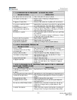

45.
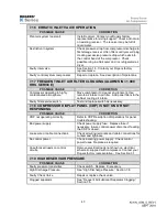
pass through the fan, then the cooler cores, and finally
exit the compressor cabinet. See Section 6.1m.
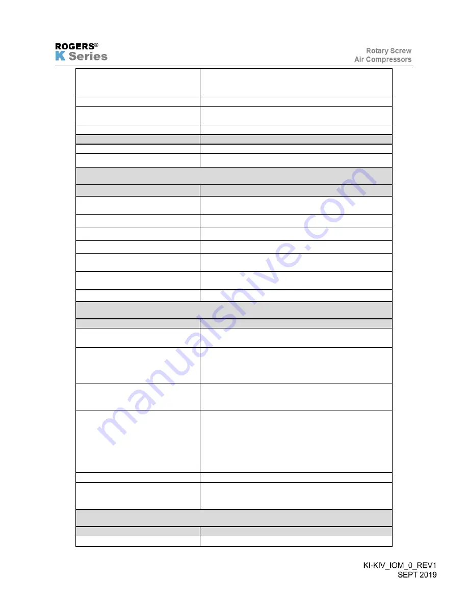
Improper lubricant.
Use recommended lubricants only—see Section 4.0
Faulty temperature regulating
valve.
Repair or replace as necessary.
Faulty sensors.
Check and replace. See Description of Operation.
POSSIBLE CAUSE
CORRECTION
Air end failure.
Contact your Rogers factory representative.
Incorrect cooler installation.
Contact your Rogers factory representative.
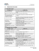
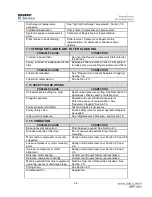
7.10 COMPRESSOR DOES NOT LOAD
POSSIBLE CAUSE
CORRECTION
Improper pressure setting.
Correct pressure set points entered. See Description
of Operation.
Loose wiring connection.
Check and tighten wiring terminals.
Faulty air inlet valve assembly.
Check and repair air inlet valve.
Faulty unloading solenoid valve.
Repair or replace as necessary.
Faulty differential pilot valve or ice
in valve.
Orifice plugged, clean or replace as necessary.
Faulty control air regulator /
setting.
Replace, service, and/or set regulator.
Clogged control air filter.
Clean or replace filter element.
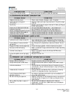
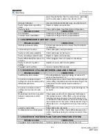
7.11 EXCESSIVE CYCLING BETWEEN LOAD AND UNLOAD
POSSIBLE CAUSE
CORRECTION
Insufficient system volume.
Provide additional volume by adding air receiver to
system. See Section 2.12.
Air pressure load and unload
settings too near the setting of the
differential pilot valve.
Set load pressure set point lower than differential pilot
valve setting. Separate load and unload settings in the
Compressor Control panel. See Description of
Operation.
Air pressure load and unload
settings are too close to each
other.
Reset load and unload settings. Typical settings are 10
psi apart
Downstream restriction in system
between compressor and air
receiver.
Check pressure drop from compressor discharge to
first storage receiver. Often filters or dryers will plug
creating excessive pressure drop which reduces the
control band of the compressor control and may cause
the compressor to short cycle. Check possible icing in
aftercooler and / or refrigerated air dryer. See section
7.16
Leaks in control lines.
Check and repair any leaks.
Contaminants in control system.
Drain lines, service filter, check differential pilot valve
orifice. Install heat tracing in cold environments (if due
to ice).
7.12 EXCESSIVE WATER IN PLANT AIR DISTRIBUTION SYSTEM
POSSIBLE CAUSE
CORRECTION
Clogged moisture separator/trap.
Clean or replace as required. See Section 2.9.
Содержание KI Series
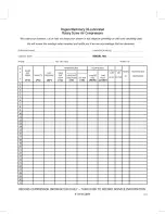
Страница 1: ...1 Model __________________ Serial __________________ Rotary Screw Air Compressors...
Страница 8: ...7 INTENTIONALLY BLANK...
Страница 9: ...8 CHAPTER 1 GENERAL INFORMATION...
Страница 19: ...10 CHAPTER 2 INSTALLATION INSTRUCTIONS...
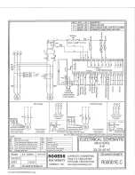
Страница 26: ...17 CHAPTER 3 ELECTRICAL INFORMATION...
Страница 30: ...21 CHAPTER 4 COMPRESSOR LUBRICANT...
Страница 39: ...30 INTENTIONALLY BLANK...
Страница 40: ...31 CHAPTER 5 AIR INLET FILTER INFORMATION...
Страница 43: ...34 INTENTIONALLY BLANK...
Страница 44: ...35 CHAPTER 6 COMPRESSOR OPERATIONS...
Страница 49: ...40 INTENTIONALLY BLANK...
Страница 50: ...41 CHAPTER 7 TROUBLESHOOTING...
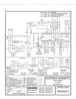
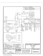
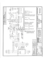
Страница 57: ...48 CHAPTER 8 FORMS RECORDS AND ELECTRICAL SCHEMATICS...
Страница 58: ...49...
Страница 59: ...50...
Страница 60: ...51...
Страница 61: ...52...
Страница 62: ...53...
Страница 63: ...54...
Страница 64: ...55...
Страница 65: ...56 INTENTIONALLY BLANK...
Страница 66: ...57...


