Rogers KI Series Скачать руководство пользователя страница 50


41. 


CHAPTER 7 


TROUBLESHOOTING  


Содержание KI Series

Страница 1: ...1 Model __________________ Serial __________________ Rotary Screw Air Compressors...

Страница 2: ...ating the compressor hearing and eye protection is required Failure to comply can cause hearing loss and serious eye damage or vision loss Do not allow flammable toxic or corrosive gases to enter the...

Страница 3: ...rstand and comply with all posted WARNING CAUTION and DANGER placards placed on the K Series compressor system This equipment contains many possibilities for injury or death to personnel if care is no...

Страница 4: ...AULT HISTORY and the Description of Operation Display and Controls Manual A list of replacement service and repair parts are listed in the Parts List manual specific to the model of your compressor Co...

Страница 5: ...perating Pressure with Standard Motor Page 9 CHAPTER 2 INSTALLATION INSTRUCTIONS 2 0 INSTALLATION 2 1 General Page 11 2 2 Location Page 11 2 3 Foundation Page 11 2 4 Compressor Rotation Page 11 V Belt...

Страница 6: ...tial start up Page 37 6 3 Stopping Unit normal shut down Page 37 6 4 Service intervals Page 38 6 4 1 Daily Checks Unit Running at Operating Conditions Page 38 6 4 2 When Required by Indicators or gaug...

Страница 7: ...ge 47 CHAPTER 6 FORMS RECORDS AND ELECTRICAL SCHEMATICS Important Shipping Bracket Information Rogers KI and KIV Record Card KI and KIV Series Rotary Screw Air Compressor Start Up Report Electrical Sc...

Страница 8: ...7 INTENTIONALLY BLANK...

Страница 9: ...8 CHAPTER 1 GENERAL INFORMATION...

Страница 10: ...OTE The cycle of intake compression and discharge occurs five times during each 360 degree rotation of the cambered rotor As shown in Figure 1 the compressor consists of two rotors within a casing The...

Страница 11: ...leaves the compressor assembly An air receiver with an effective drain valve can also serve this purpose The quantity of air entering the compressor is regulated by the inlet valve located between the...

Страница 12: ...ure Control Valve 3 Oil Filter Element 4 Intake Air Filter Ambient Air 5 Drive Shaft 6 Oil Drain Valve 7 ASME Safety Relief Valve 8 Oil Level Gauge Not Shown 9 Pressure Gauge 10 Separator Scavenging T...

Страница 13: ...Head and Temperature Control Valve 3 Oil Filter Element 4 Intake Air Filter Ambient Air 5 Inlet Check and Unloading Valve 6 Drive Shaft 7 Oil Drain Valve 8 Oil Level Gauge Not Shown 9 ASME Safety Reli...

Страница 14: ...of both the male and female rotor and the compression chamber to seal the internal clearances lubricate the rotors and absorb most of the heat generated during compression of the air The lubricant and...

Страница 15: ...omatic and only adjustable by changing the thermal control element When the lubricant temperature is low the lubricant enters the valve at port 1 marked IN from sump and flows partially to the cooler...

Страница 16: ...rred to as a Top Hat style separator system The lubricant separator reservoir contains an air lubricant separator element beneath the tank s lid As air lubricant mixture enters the reservoir most of t...

Страница 17: ...open allowing control air to close the inlet valve When the compressor is loaded the control solenoid is energized and the control air valve is closed bleeding off the control air allowing the inlet...

Страница 18: ...combinations When resetting operating pressures adjust pressure upward while observing an ammeter reading on all phases compared to motor nameplate limits See Table 3 Table 3 Maximum Operating Pressu...

Страница 19: ...10 CHAPTER 2 INSTALLATION INSTRUCTIONS...

Страница 20: ...compression Obstruction of the cooling air inlet and outlet areas of the compressor cabinet will negatively affect the reliability and performance of the compressor Ideally the cooling air is ducted...

Страница 21: ...HP are equipped with an automatic belt tensioning device and requires no adjustments between belt replacements Belt tension is established by springs between the compressor assembly base and the motor...

Страница 22: ...be carefully checked whenever V belts are replaced Mount the sheaves close to the compressor and motor housing to reduce strain on bearings from side load 2 6 D Face Mounted Drive System 60 to 100 HP...

Страница 23: ...ve cleaning protect electrical components such as the motor and starter and pressure wash cooler cores from both sides taking care to avoid damage to aluminum fins and fan blades Wipe all fan blades c...

Страница 24: ...T use plastic pipe or rubber hose s in any part of the main air distribution system Doing so may result in serious injury to personnel and damage to equipment The maximum recommended CFM free air for...

Страница 25: ...ve for proper sizing of a receiver for your application Do not connect a rotary screw compressor on the same air line with a reciprocating unit before the air receiver The pulsating pressure generated...

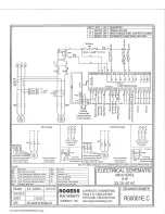
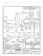
Страница 26: ...17 CHAPTER 3 ELECTRICAL INFORMATION...

Страница 27: ...or Overload setting Control Panel Setting Change The KI 60 100 HP and all KIV compressors are 460 volt only 3 1 2 Steps for Voltage Conversion WARNING The following procedures must be performed by qua...

Страница 28: ...be changed by switching any two of the three electrical supply leads with each other in the main connection terminal See table 8 for correct rotation of various models 3 3 Blowdown Valve The sump blow...

Страница 29: ...for lubrication data Care should be exercised when lubricating 3 5 Local Display See KI and KIV Series Description of Operations Display and Controls manual for a full description of features paramet...

Страница 30: ...21 CHAPTER 4 COMPRESSOR LUBRICANT...

Страница 31: ...e compressor and relieve pressure from the unit before adding lubricant Not doing so may result in death or injury to personnel and damage to equipment NOTE Alternative lubricants may have different c...

Страница 32: ...factory representative for recommendations Completely drain lubricant while hot from every component that contains lubricant 1 Replace lubricant filter and separator 2 Fill machine with a factory app...

Страница 33: ...system The air compressor rotors run at close clearances and could be severely damaged by foreign material 4 5 3 Changing Lubricants When changing lubricant always drain all components as thoroughly...

Страница 34: ...el right hand label in Figure 2 to the outside of the mailer and place it in the mail Figure 1 Lubricant Test Labels 4 6 Lubricant Filter The lubricant filter shown below is a spin on full flow type h...

Страница 35: ...or the lubricant filter To replace the separator element 1 Lock Out Tag Out the Equipment and ensure that the service valve at the discharge of the compressor has been closed Vent the air between the...

Страница 36: ...are should be taken in handling the elements to avoid damage DO NOT remove the ground staples in the gaskets for safety reasons Replace the lubricant separator elements after every 3 000 hours of oper...

Страница 37: ...centered on bolts Be sure to use new gaskets with metal staples in each The purpose of the staple is to ground the separator element to prevent electrostatic buildup 7 Inspect bolts for proper thread...

Страница 38: ...tube positioned inside the lubricant separator element and via a tube to the compressor or inlet valve Cleaning of the scavenging system should be performed 1 When no lubricant is seen moving through...

Страница 39: ...30 INTENTIONALLY BLANK...

Страница 40: ...31 CHAPTER 5 AIR INLET FILTER INFORMATION...

Страница 41: ...ep foreign material from entering the compressor A pleated cellulose element within the filter housing should be changed every 1 000 hours In a dirty environment the element can be blown out more freq...

Страница 42: ...re in the compressor has been drained to zero 0 psig An open vent or drain will verify compressor pressure is zero 0 psig 2 Remove cover from filter housing unscrew element retaining nuts and withdraw...

Страница 43: ...34 INTENTIONALLY BLANK...

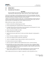
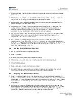
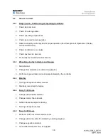
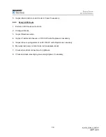
Страница 44: ...35 CHAPTER 6 COMPRESSOR OPERATIONS...

Страница 45: ...mounting pads Do not use the wooden shipping pallet as a permanent mounting base 4 Ample cooling air and ventilation is provided 5 Verify proper lubricant level in sight tube 6 Verify air end turns ov...

Страница 46: ...ly the compressor will shut down at 235 F 113 C RESET THE FAN TEMPERATURE TURN ON SET POINT BACK TO FACTORY SETTINGS 60 F 16 C 6 2 Starting Unit After Initial Start Up 1 Ensure lubricant is present in...

Страница 47: ...When Required by Indicators and Gauges 1 Add lubricant 2 Change filter elements air lubricant separator 3 Perform any prescribed service intervals indicated by the controller 6 4 3 Monthly 1 Test hig...

Страница 48: ...3 Inspect blowdown valve 4 Inspect V belts and sheaves on 10 50 HP units Replace as necessary 5 Inspect drive coupling element on 60 100 HP units Replace as necessary 6 Manually test reservoir relief...

Страница 49: ...40 INTENTIONALLY BLANK...

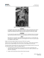
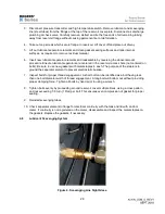
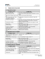
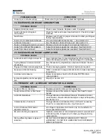
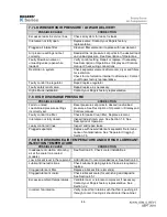
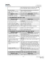
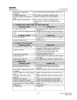
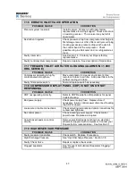
Страница 50: ...41 CHAPTER 7 TROUBLESHOOTING...

Страница 51: ...larm Start Delay Timer is still counting down Wait for counter to reach zero 7 2 UNSCHEDULED SHUTDOWN POSSIBLE CAUSE CORRECTION High air discharge temperature see High Discharge Air Temperature Sectio...

Страница 52: ...tween Load and Unload Section 7 11 Plugged or broken scavenging lines Check scavenging system Clean or replace as required Excessive lubricant foaming Water in lubricant Change lubricant and or increa...

Страница 53: ...tings incorrectly set Reset pressure set points to desired load unload pressures See Description of Operation Display and Controls manual Faulty control line filter Check for leaks Clean filter Replac...

Страница 54: ...SSIBLE CAUSE CORRECTION Insufficient system volume Provide additional volume by adding air receiver to system See Section 2 12 Air pressure load and unload settings too near the setting of the differe...

Страница 55: ...Display and Controls Manual Plugged separator Replace with new air lubricant separator Determine cause of contamination See Separator Clogging Section 7 6 Faulty pressure transmitter Test and replace...

Страница 56: ...Add panel filters to the cabinet cooling air intake Faulty filter service switch Test and replace switch as necessary 7 18 COMPRESSOR DISPLAY PANEL CDP IS NOT ON OR NOT RESPONDING POSSIBLE CAUSE CORR...

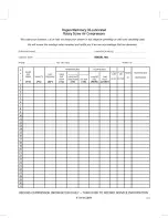
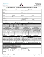
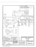
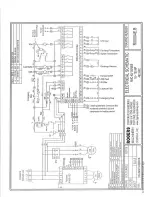
Страница 57: ...48 CHAPTER 8 FORMS RECORDS AND ELECTRICAL SCHEMATICS...

Страница 58: ...49...

Страница 59: ...50...

Страница 60: ...51...

Страница 61: ...52...

Страница 62: ...53...

Страница 63: ...54...

Страница 64: ...55...

Страница 65: ...56 INTENTIONALLY BLANK...

Страница 66: ...57...

Отзывы: