


9
1.4. Oil Flow for Lubrication
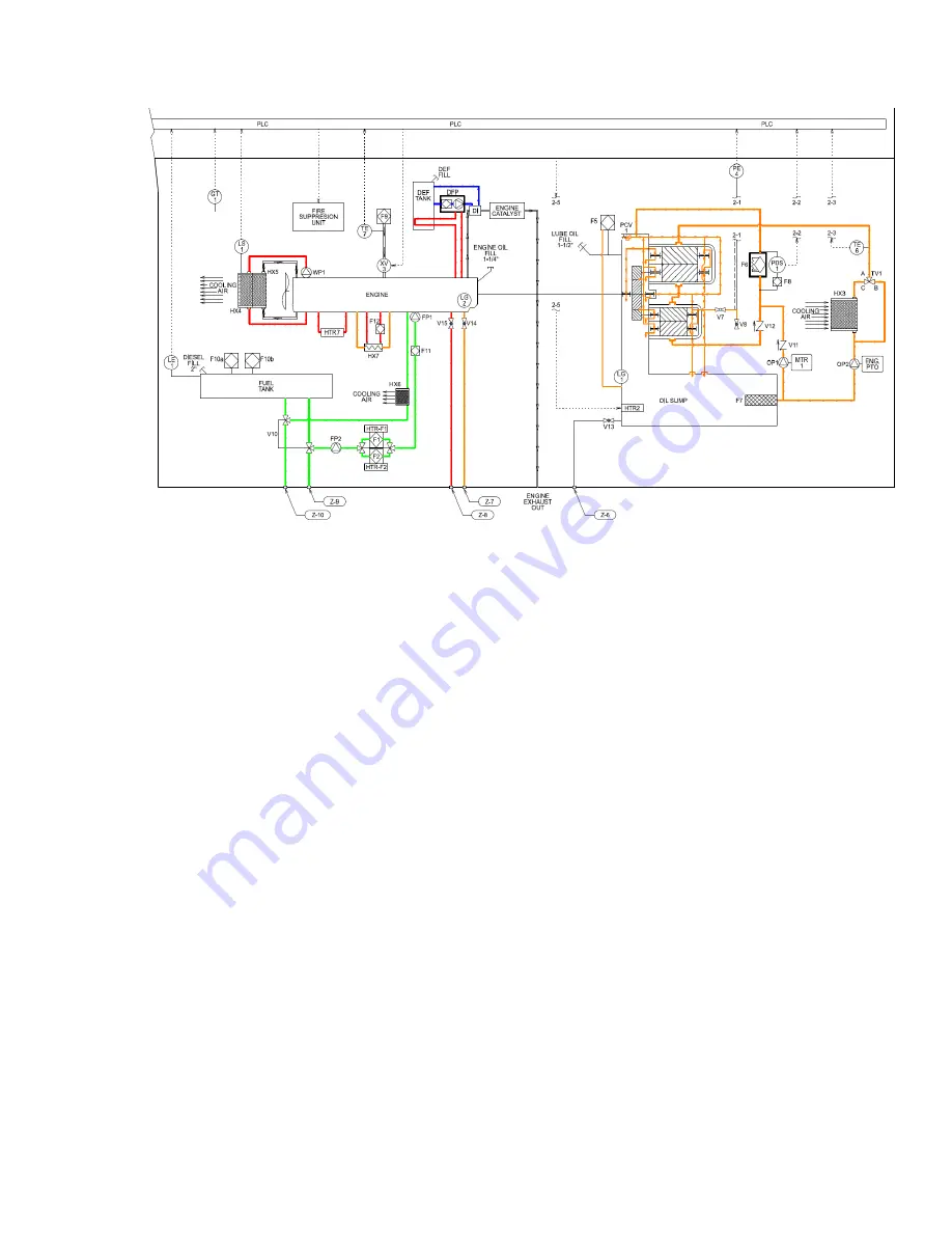
FIGURE 3 - OIL FLOW
Oil for bearing and gear lubrication is stored in the oil sump, located in the lower section
of the main gear case/compressor housing. A sight gauge, located on the side of the oil
sump, is provided to check oil level. Lube oil is drawn from the sump by a separate
motor-driven oil pump (OP1) during start-up, then transitions to be run by a PTO-driven
pump after the Diesel engine starts. A check valve on the outlet of the electric oil pump,
and upstream of the oil filter prevents backflow. A strainer (F7) is provided in the oil
sump on the oil pump suction line.
An oil thermostatic valve (TV1) and air-cooled oil cooler (HX3) control oil temperature to
approximately 115°F (45°C). Cooled oil enters the compressor 1st stage cooling jacket
then the 2nd stage cooling jacket. The oil is then filtered by a high efficiency microglass
oil filter, featuring a full flow design incorporating a spin-on filter element and an internal
relief valve. A differential pressure gauge with switch (PDS1) is used to check oil filter
Δ
P
and generate an HMI alert to service the oil filter.
After filtration the oil enters the compressor oil passages. An oil pressure control valve
(PCV1) is provided to regulate a constant pressure for component lubrication by
returning excess oil back to the sump. The oil flows through internal passages, and
external tubing, to lubricate all bearings, timing gears, and drive gears.
An oil pressure transmitter (2-1) is wired to the PLC to monitor the lube oil pressure. Oil
pressure is monitored for alarm shutdown if oil pressure can not be achieved during
starting or is too low while the compressor is operating. A block valve (V7) and sample
valve (V8) are provided to test the operation of the alarm.
Содержание GPKD-1550-H
Страница 2: ...2 THIS PAGE LEFT BLANK...
Страница 22: ...22 Note The design of the oil pan is not the extended type as shown in the diagram FIGURE 10b ENGINE RIGHT SIDE...
Страница 47: ...47...
Страница 48: ...48 THIS PAGE LEFT BLANK...