28
3. Start-Up
3.1. Pre-start Checks
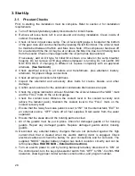
Prior to starting, the installation must be complete. Refer to section 2 for installation
requirements.
a. Turn off barrel-style battery safety disconnects for initial checks.
b. Remove all loose items left in and around unit during installation. Clean inside of
cabinet if necessary.
c. Check oil level in gear case sump. The oil level sight gauge is located at the bottom
of the gear case and can be checked by opening the left front door. The oil level must
be maintained between the Min. and Max. lines. Note: If the compressor has been off
for an extended time the oil may be at or above the Max line due to oil draining back
from the cooler. Check oil level again after the oil pump has been started.
If necessary, add oil. Oil type for initial fill is shown on a label on the sump breather
housing. Do not remove oil fill plug while compressor is running. Do not overfill. DO
NOT MIX OILS. If changing to different oil, replace completely with an approved
alternate.
(See Section 6)
d. Check electrical wiring to all motors and transformers, plus alternator, battery,
alternator, for proper voltage connections.
e. Check all wiring connections for tightness.
f. Inspect the alternator and accessory drive belts for cracks, breaks, and other
damage.
g. Confirm service valves for the automatic condensate drain valves are open.
h. Check the engine lubrication oil level. Maintain the oil level between the “ADD” mark
and the “FULL” mark on the oil level gauge.
i. Check the coolant level. Observe the coolant level in the coolant recovery tank
(above the radiator pack). Maintain the coolant level to the “FULL” mark on the
coolant recovery tank.
j. Ensure that the 3-way fuel valve petcock is set to “INT” for the internal tank, “EXT” for
an external source. “OFF” shuts off all fuel supplies. Drain water from the water
separator.
k. Ensure that the areas around the rotating parts are clear.
l. All of the guards must be put in place. Check for damaged guards or for missing
guards. Repair any damaged guards. Replace damaged guards and/or missing
guards.
m. Disconnect any external battery chargers that are not protected against the high
current drain that is created when the electric starting motor is engaged. Check
electrical cables and check the battery for poor connections and for corrosion. The
supplied “NOCO” integral battery charger has built-in isolation circuitry and can be
left in place (
See FIGURE 6A/B – External Connections
).
n. Turn on electric power to unit by turning barrel-style battery disconnect to “ON”. At
the control panel, turn the key-style selector switch from “OFF” to “ON”. Confirm HMI
operation, showing proper model number, serial number, and program number.
Содержание GPKD-1550-H
Страница 2: ...2 THIS PAGE LEFT BLANK...
Страница 22: ...22 Note The design of the oil pan is not the extended type as shown in the diagram FIGURE 10b ENGINE RIGHT SIDE...
Страница 47: ...47...
Страница 48: ...48 THIS PAGE LEFT BLANK...


