


25
CAUTION:
Do not install an additional check valve between the compressor and the
plant compressed air system piping. Doing so will prevent correct
compressor operation and may damage the compressor.
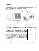
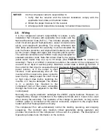
A flexible connection is required between the outlet of the compressor and the plant
compressed air system piping. The outlet air piping must be properly supported to
prevent strain on the compressor piping or cabinet. For safe servicing of the compressor
a manual isolating valve is installed in the outlet air piping at a convenient location close
to the compressor (
see FIGURE 6A, FRONT VIEW
).
Condensation will occur in the downstream piping. Vertical pipe runs, and low points in
the piping system, should be equipped with drop legs and drains for moisture traps. If
multiple compressors are piped into a common discharge header, the connections from
the compressors should be to the top of the header. The header should be equipped
with drop legs and drains for moisture traps. See FIGURE 13.
Содержание GPKD-1550-H
Страница 2: ...2 THIS PAGE LEFT BLANK...
Страница 22: ...22 Note The design of the oil pan is not the extended type as shown in the diagram FIGURE 10b ENGINE RIGHT SIDE...
Страница 47: ...47...
Страница 48: ...48 THIS PAGE LEFT BLANK...