PowerFlex Digital DC Drive User Manual -
Publication 20P-UM001C-EN-P - July 2008
Appendix
B
HIM Overview
External and Internal
Connections
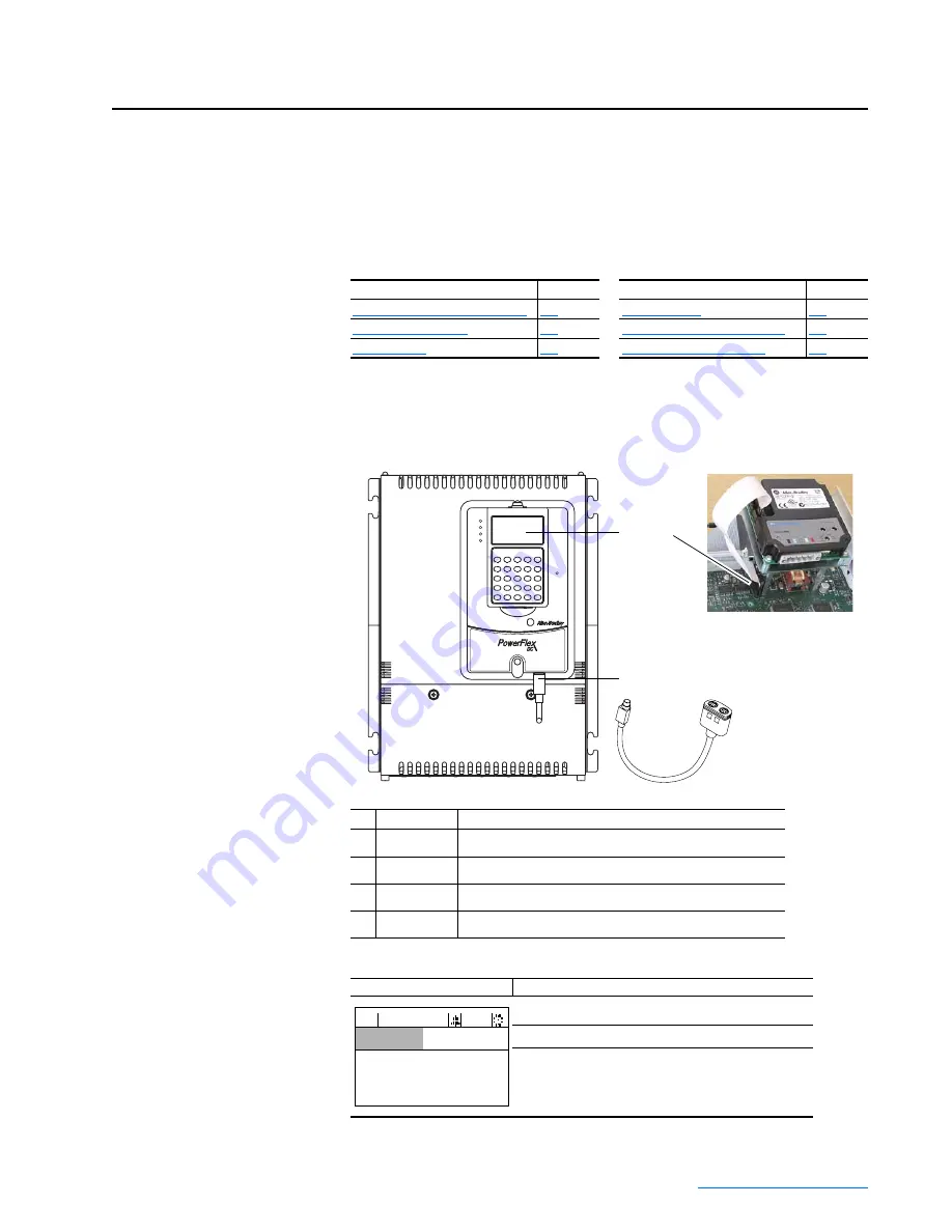
The PowerFlex DC drive provides a number of cable connection points for
the HIM (Frame A shown).
LCD Display Elements
The top line of the HIM display can be configured with parameter 1321 [DPI Fdbk Select].
For information on . .
See page
For information on . .
See page
External and Internal Connections
Viewing and Editing Parameters
No. Connector
Description
➊
DPI Port 1
HIM connection when installed in cover.
➋
DPI Port 2
Cable connection for handheld and remote options.
➌
DPI Port 3 or 2 Splitter cable connected to DPI Port 2 provides additional port.
➍
DPI Port 5
Cable connection for communications adapter.
2
1o
r3
➋
➍
➌
STS
PORT
MOD
NET A
NET B
➊
Front cover removed
Display
Description
Direction
⎥
Drive Status
⎥
Alarm
⎥
Auto/Man
⎥
Information
Commanded or Output Speed or Current
Programming / Monitoring / Troubleshooting
F-> Power Loss
Auto
0.0
RPM
Main Menu:
Diagnostics
Parameter
Device Select
Содержание PowerFlex series
Страница 1: ...USER MANUAL Firmware Version 1 006 2 001 PowerFlex Digital DC Drive ...
Страница 190: ...PowerFlex Digital DC Drive User Manual Publication 20P UM001C EN P July 2008 A 22 Supplemental Drive Information Notes ...
Страница 292: ...Index 24 PowerFlex Digital DC Drive User Manual Publication 20P UM001C EN P July 2008 ...
Страница 293: ......


