Technical assistance and maintenance
Ed. 04/2007
39
5.3 MAINTENANCE
Careful maintenance is always at the basis of economy and safety.
Maintenance for heating units must be carried out, preferably at the beginning of winter,
by qualified service engineers
.
For correct, prolonged operation, general cleaning of the appliance is recommended at
least once a year (giving particular attention to the heat exchangers and fan grilles), as
well as combustion tests as applicable under specific regulations.
5.4 OPERATING ANOMALIES
Before checking for possible failures, ensure that:
A) Correct electric supply: 230-240V ±10% 50Hz and adequate earthing are provided.
B) The gas is supplied.
C) Pressures and flows are within the limits recommended by the manufacturer. A
pressure lower than the given limits will result in insufficient gas inlet. The causes for
this may be the following:
If the unit is fed with natural Gas:
a) Poor gas meter performance.
b) The length of the pipes and the number of elbows are excessive with respect to the
diameter.
If the unit is fed with L.P.G.:
a) It can happen that after the first time the burner turns off, the unit locks out at the
moment of ignition. In this case it may be that the reducer flow is insufficient.
b) If the required pressure is not reached, it may be either that the meter does not
provide adequate flow or the length of the pipes and the number of elbows are
excessive with respect to the diameter.
Only at this point proceed with the specific trouble shooting.
WARNING
Before opening the side door to access the control panel, CUT OUT THE
POWER SUPPLY to the unit using the omnipolar switch.
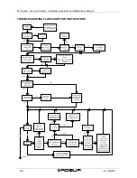
5.5 TYPES OF FAULT AND POSSIBLE ACTIONS
In case of a failure, call a qualified service engineer.
CASE NO. 1: THE UNIT LOCKS OUT DURING THE FIRST IGNITION
PHASE.
D) The ignition electrode is broken or badly positioned.
E) The flame sensor is broken or incorrectly positioned or touches the unit ground.
NOTE
For correct burner ignition, the distance of the ignition electrode from the burner head
should be between 4 mm and 6 mm.

