M C Series – Warm air heaters – Installation, Operation and Maintenance Manual
28
Ed.
04/2007
4.
Connect the heater to the power supply and switch it on.
5.
Close the gas valve and check that after a few seconds the arrest warning light A
comes on (see Figure 2).
6.
Open the gas valve again, push the reset button B (see Figure 2) and check that the
arrest warning light switches off and that the heater starts up again.
)
The control cables (in particular the one connecting the heater to the control box)
must be protected from interference produced by the power cables
. This
protection can be obtained for example by shielding the cables or by running them
through channels which are separate from those of the power cables.
)
The maximum length of the cable connecting the heater to the control box is 20
metres.
4.3 HOW TO CONNECT THE THERMOSTAT TO THE HEATER
For the operation of the heater it must be connected to an ambient thermostat (available
as an accessory). For the installation of the ambient thermostat, follow the instructions
below.
You will need:
the heater installed.
Electrical connections must be made by
professionally qualified personnel
. In
any case, before making the electrical connections, make sure that the wires are
not live.
1.
Locate the position where the ambient thermostat is to be installed, if possible
approximately 1.5 metres from the floor, away from draughts, direct sunlight, and
direct heating sources (light bulbs, flows of hot air from the appliance itself, etc.) and
if possible NOT on outer walls, in order not to falsify the temperature readings and
therefore the operation of the appliance. IN THIS WAY THE APPLIANCE WIL BE
PREVENTED FROM STARTING AND STOPPING WHEN NOT DESIRED, THUS
GUARANTEEING OPTIMAL COMFORT LEVELS IN THE ROOM. If this is not
possible, shield the ambient thermostat by placing a sheet of insulating material (e.g.
cork, polystyrene, etc.) between it and the wall.
2.
Fix the ambient thermostat to the wall.
3.
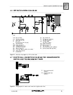
Connect the ambient thermostat to the terminal board of the heater following the
instructions provided in Figure 18 on page 30.


