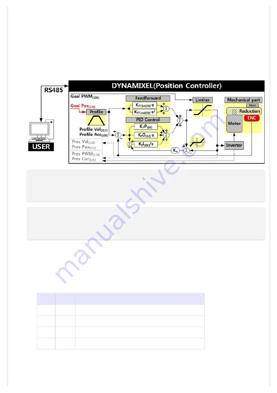
4. Feedforward and PID controller calculate PWM output for the motor based on desired
trajectories.
5.
sets a limit on the calculated PWM output and decides the final PWM
value.
6. The final PWM value is applied to the motor through an Inverter, and the horn of
DYNAMIXEL is driven.
7. Results are stored at
Present Velocity(128)
,
.
NOTE
: In case of PWM Control Mode, both PID controller and Feedforward controller are deactivated
while
value is directly controlling the motor through an Inverter. In this manner, users
can directly control the supplying voltage to the motor.
NOTE
: K
a
is an Anti-windup Gain that cannot be modified by users.
For more details about the PID controller and Feedforward controller, please refer to the
Bus Watchdog (98) is available from firmware v38. It is a safety device (Fail-safe) that stops the
DYNAMIXEL if the communication between the controller and DYNAMIXEL communication
(RS485, TTL) is disconnected due to an unspecified error. Communication is defined as all the
Instruction Packet in the DYNAMIXEL Protocol.
Values Description
Unit
20[ms]
-
Range 0
Deactivate Bus Watchdog Function, Clear Bus Watchdog Error
Range 1 ~ 127 Activate Bus Watchdog
Range -1
Bus Watchdog Error Status
The Bus Watchdog function monitors the communication interval (time) between the controller
and DYNAMIXEL when
is ‘1’. If the measured communication interval (time)
is larger than
to ‘-1’ (Bus Watchdog Error). If the Bus Watchdog Error screen appears, the Goal Value (
Содержание Dynamixel X Series
Страница 27: ...3 1 Wiring through Back Case New XL430 W250 Released on 2018 3rd quarter ...
Страница 28: ...Old XL430 W250 This type has been discontinued ...
Страница 30: ......
Страница 31: ...3 2 2 Old XL430 W250 ...


