background image

SPIROR HP - DR

Mineral oil

+32°C/+50°C -460 CST/40°C

MELLANA OIL 460 IP

SPARTAN EP 460 ESSO

BLASIA 460 AGIP

MOBILGEAR 634 MOBIL

OMALA EP 460 SHELL

ENERGOL GR-XP 460 BP

Worm gear motor

Grease

TELESIA COMPOUND B IP

STRUCTOVIS P LIQUID KLUBER

TOTALCARTER SYOO TOTAL

Gear and worm gear motor

Synthetic oil

TELESIA OIL IP

SYNTHESO D 220 EP KLUBER

BLASIA S 220 AGIP

Gear and worm gear motor

Lithium grease

ALVANIA R2 SHELL

HL 2 ARAL

ENERGREASE LS2 BP

BEACON 2 ESSO

MOBILIX MOBIL

Bearings with support

Synthetic oil

-5°C / +5°C VG 68 (SAE 20)

+5°C / +25°C VG 100 (SAE 30)

Reel carriage lifting

chain

Synthetic oil

+25°C/+45°C VG 150 (SAE 40)

+45°C/+70°C VG 220 (SAE 50)

Table rotation chain

|

Important

Do not mix oils of different makes and specifications.

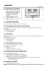
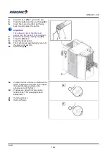
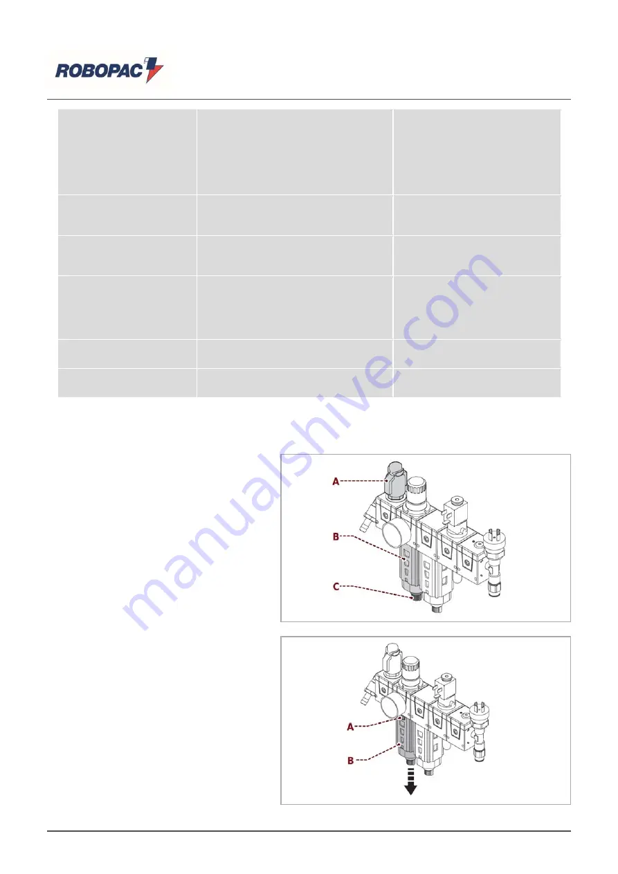
7.5. DRAINING THE

CONDENSATE

Proceed as indicated.

1.

Close the tap

(A)

and control the level of

condensation in the container

(B)

.

2.

Unscrew, if necessary, the valve

(C)

to

empty condensation.

3.

Push the valve

(C)

up until all

condensation is removed.

4.

Tighten the valve

(C)

.

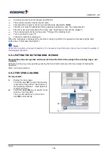
7.6. CLEANING THE FILTER

Proceed as indicated.

1.

Push the

(A)

switch downward and

rotate the

(B)

cup until the point of

extraction.

2.

Disassemble the filter and clean it with

compressed air. Wash it, if necessary,

with water and non-aggressive

detergents.

3.

Reassemble the filter.

4.

Reinsert the cup, rotate it and block it

with the

(A)

switch, switching it upwards.

English

83/95

Содержание SPIROR DR

Страница 1: ... or double DR plastic film reel SPIROR HP DR Translation of the original instructions Code 3709303158 0 Edition 0917 ____________ SERIAL NUMBER ____________ ATTENTION Read and understand these instructions before using the machine Keep this handbook for further consultation ROBOPAC S p A ...

Страница 2: ...3 2 DESCRIPTION OF THE OPERATION CYCLE 3 2 1 TOTAL WRAPPING 3 2 2 HEAD TAIL WRAPPING 3 2 3 COMPLETE WRAPPING AND CENTRAL BANDS 3 2 4 HEAD TAIL AND CENTRAL BELTS WRAPPING 3 3 SAFETY DEVICE DESCRIPTIONS 3 4 DESCRIPTION OF THE ELECTRICAL DEVICES 3 5 PNEUMATIC DEVICE DESCRIPTION 3 6 ACCESSORIES AVAILABLE UPON REQUEST 3 7 TECHNICAL SPECIFICATIONS Spiror HP Spiror DR 3 7 1 PRODUCT SIZE 3 7 2 FILM SPECIF...

Страница 3: ...EGULATION OF VALUES 6 4 3 COPY RECIPES FUNCTION 6 5 CYCLE PARAMETER SETTING RECIPE COMPOSITION 6 6 WRAPPING CYCLE RESET 6 7 MACHINE CONDITIONS 6 7 1 MACHINE ISOLATED FROM THE POWER SUPPLIES 6 7 2 MACHINE ON 6 7 3 MACHINE READY FOR THE CYCLE 6 8 MACHINE OPERATION PREPARATION 6 9 MACHINE STARTING 6 9 1 PUTTING THE ROTATING RING IN PHASE 6 9 2 FILM SPOOL LOADING 6 9 3 INSERT THE FILM IN THE CLAMP 6 1...

Страница 4: ...PARTS 9 2 FILM CUTTING BLADE REPLACEMENT 9 3 REPLACE ROTATING RING BELT 9 4 FUSE REPLACEMENT 9 5 LIST OF ESSENTIAL SPARE PARTS 9 6 MACHINE DISPOSAL AND SCRAPING 10 ENCLOSED DOCUMENTATION 10 1 WARRANTY CONDITIONS 10 2 PNEUMATIC CIRCUIT DIAGRAM SPIROR HP 10 3 PNEUMATIC CIRCUIT DIAGRAM SPIROR DR English 4 95 ...

Страница 5: ...ion of its useful life in a well known and easy to access place available for reference any time the need should arise In order to easily consult the specific topics of interest check the table of contents Some information may not correspond completely to the actual configuration of the machine delivered Any additional information does not affect the readability of the text and the safety level Th...

Страница 6: ...rson authorised and chosen among those who have the requirements skills and information necessary to perform ordinary and extraordinary machine maintenance He is expected therefore to possess precise information and skills with particular expertise in the field of intervention Format Change series of operations to carry out on the machine before starting to work with the machine with different cha...

Страница 7: ...ls of installed commercial devices if necessary for machine use Quick start guide USB flash drive that contains the information listed Use and maintenance manual translated into various languages Spare parts catalogue Machine programming software Electrical wiring diagram 1 6 HOW TO READ THE DIRECTIONS FOR USE The handbook is divided in chapters each of which describes a specific category of infor...

Страница 8: ... them priorily on the type of work and the behaviour to be used The machine must be handled with the aid of specific means crane forklift etc by qualified personnel capable of observing the safety requirements When using the lifting means insert and or fasten the devices hooks forks etc ONLY into the points provided on the package and or the machine Transport the machine suitable means of adequate...

Страница 9: ...he risks related to assistants involvement you must inform them priorily on the type of work and the behaviour to be used Make sure that no foreign persons are present within the machine operating area during its production activity and maintenance Do not use the machine if the scheduled maintenance work has not been regularly carried out DO NOT continue to use the machine if malfunctions have bee...

Страница 10: ...ning and building the machine the manufacturer has paid particular attention to the RESIDUAL RISKS that may affect the safety and health of the operators The residual risks are all the risks that persists although all safety solutions have been applied and integrated during machine design The manufacturer has complied with the specific standards in force and applied all the good manufacturing regu...

Страница 11: ... guard door open see figure Other risks Danger of crushing of arms and legs if entering the machine from infeed or outfeed through the net protections Danger of cutting with the cutting arm blade if you enter the machine when the latter is stationary English 11 95 ...

Страница 12: ...h current regulations on the matter Select the components according to the chemical and physical features of the material and carry out the differentiated waste disposal as per the standards in force Follow the procedures in this chapter Non compliance with the instructions given may cause risks for safety and health of the persons and economic damages 2 7 SAFETY WARNING FOR ELECTRICAL EQUIPMENT T...

Страница 13: ...oints with a fork device C Danger sign indicates a cutting hazard D Information sign indicates the direction of rotation of the ring E Information sign it indentified the power cut off switch H Information signal indicates the film layout L Mandatory sign it indicates the obligation to read the entire documentation before using the machine M Information signal identifies the pneumatic disconnectin...

Страница 14: ...SPIROR HP DR Important Check that the plates are clearly readable and if necessary replace them with new ones that shall be positioned in the same places as previously English 14 95 ...

Страница 15: ...he beginning and end of the cycle It is only valid for the HP 400 600 900 models and as option for the DR 400 600 900 models F Film cutting unit cuts film at wrapping cycle end It is only valid for the HP 400 600 900 models and as option for the DR 400 600 900 models G Product infeed unit conveys the product from infeed to outfeed of machine Available in the following lengths 500 1500 and 2500 In ...

Страница 16: ...SPIROR HP DR SPIROR HP SPIROR HP 300 SPIROR HP 400 600 English 16 95 ...

Страница 17: ...SPIROR HP DR SPIROR HP 900 SPIROR DR SPIROR DR 400 600 Optional English 17 95 ...

Страница 18: ...SPIROR HP DR SPIROR DR 400 600 SPIROR DR 900 Optional SPIROR DR 900 English 18 95 ...

Страница 19: ...series of additional loops at the head at the tail and with a series of reinforcement strappings spaced by a programmable time 4 Head tail and central belts wrapping The product head and tail are wrapped with a series of reinforcing bands spaced by a programmable time 5 Head and additional bands winding The head of the product is wrapped and a series of additional reinforcement strappings are made...

Страница 20: ...he conveyor starts and moves the product towards the rotating ring The product engages photocell B1 the infeed pressure platen lowers and blocks the product the head positioning timer starts After the timer count has finished the carrier stops the rotating ring starts counting the head and tail turns the head of the product is wrapped English 20 95 ...

Страница 21: ...product Note The overlapping of film wraps is defined by roller conveyor speed thrust bearing speed and film width Phase 3 The product moves forward disengaging photocell B1 the infeed pressure platen lifts the tail positioning timer starts After the timer count has finished the outfeed carrier stops the head and tail turns counter starts the tail of the product is wrapped and gripper comes out at...

Страница 22: ...he film and the arm with the blade makes the cut The outfeed conveyor restarts The product detects the photocell B2 the outfeed pressure unit lifts up and the conveyor outfeed timer starts When timer has finished counting the conveyor stops and the products totally wrapped can be removed from the machine English 22 95 ...

Страница 23: ...oduct engages photocell B1 the infeed pressure platen lowers and blocks the product the head positioning timer starts After the timer count has finished the carrier stops the rotating ring starts counting the head and tail turns the head of the product is wrapped At the last wrap of the rotating ring the clamp comes out to hook the film the rotating ring stops while the clamp blocks and cuts film ...

Страница 24: ...aging photocell B1 the infeed pressure platen lifts and the ring starts rotation After one revolution conveyors turn on and the tail positioning timer begins counting After the timer count has finished the outfeed carrier stops the head and tail turns counter starts the tail of the product is wrapped and gripper comes out at the last turn of the rotating ring to grasp the coating English 24 95 ...

Страница 25: ...ripper blocks the film and the arm with the blade makes the cut The outfeed conveyor restarts The product detects the photocell B2 timer begins counting the conveyor outfeed When timer has finished counting the conveyor stops and the products totally wrapped can be removed from the machine English 25 95 ...

Страница 26: ...hase 1 The conveyor starts and moves the product towards the rotating ring The product engages photocell B1 the infeed pressure platen lowers and blocks the product the head positioning timer starts After the timer count has finished the conveyor stops the rotating ring starts counting the reinforcing revolutions the head of the product is wrapped English 26 95 ...

Страница 27: ...product Note The overlapping of film wraps is defined by roller conveyor speed thrust bearing speed and film width Phase 3 The central bands timer starts counting at count completed the conveyor stops the rotating ring starts and counts the reinforcing revolutions set the product is wrapped for the number of reinforcing revolutions set Note The number of central bands is determined by the Central ...

Страница 28: ...e last turn of the rotating ring the gripper comes forward to hook the film Phase 5 After the counting of the reinforcement round the rotating ring stops while the gripper blocks the film and the arm with the blade makes the cut The outfeed conveyor restarts The product detects the photocell B2 the outfeed pressure unit lifts up and the conveyor outfeed timer starts When timer has finished countin...

Страница 29: ...ng The product engages photocell B1 the infeed pressure platen lowers and blocks the product the head positioning timer starts After the timer count has finished the carrier stops the rotating ring starts counting the head and tail turns the head of the product is wrapped At the last wrap of the rotating ring the clamp comes out to hook the film the rotating ring stops while the clamp blocks and c...

Страница 30: ... 3 The central bands timer starts counting at count completed the conveyor stops the rotating ring starts and counts the reinforcing revolutions set the product is wrapped for the number of reinforcing revolutions set Note The number of central bands is determined by the Central bands timer the speed of the carriers and the length of the product English 30 95 ...

Страница 31: ...tarts the tail of the product is wrapped and gripper comes out at the last turn of the rotating ring to grasp the coating Phase 5 After the counting of the head and tail round the rotating ring stops while the gripper blocks the film and the arm with the blade makes the cut The outfeed conveyor restarts The product detects the photocell B2 timer begins counting the conveyor outfeed When timer has ...

Страница 32: ...e power on and off It is lockable to prevent unauthorized persons from activating it while the machine is being adjusted or during maintenance B Emergency button the machine stops immediately when this button is pressed in emergency situations C Micro switch on the mobile guard stops all machine functions when opened D Fixed guards avoid access to the inner parts of the machine E General exhaust s...

Страница 33: ...ator to access the machine internally when all the components are completely stationary 3 4 DESCRIPTION OF THE ELECTRICAL DEVICES The figure shows the positioning of the devices on board of the machine A Photocell Detects the product in the infeed area B Photocell Detects the product in the outfeed area C Sensor Detects the reel in the cycle start position rotation phase HP version only C1 Sensor ...

Страница 34: ...mpressed air supply when power is disconnected 5 Progressive starter Allows you to pressurise the machine circuit gradually 6 Pressure switch It detects the line pressure when it drops below the set value and puts the machine in emergency condition 7 Solenoid valves bank Solenoid valve Commands descent ascent of pressure unit in infeed to wrapping machine Solenoid valve Commands ascent descent of ...

Страница 35: ...veyors with idle motorized roller in lengths 1500 2500 3500 mm The rollers can be galvanized PVC Polyurethane You can also request belt conveyors in lengths 1500 2500 3500 mm The conveyors can have a double function for product accumulation and further support 3 7 TECHNICAL SPECIFICATIONS Spiror HP Spiror DR The table below shows the technical specifications of the machine Spiror HP Description Un...

Страница 36: ...mensions width and height or diameter of the products cross sections workable on each machine must remain within the respective diagrams the same is to be said for the cross sections that are uniform on all the product s length For best results from a qualitative point of view the rotating ring diameter must be the smallest possible compared to the product s cross section For cross sections smalle...

Страница 37: ...SPIROR HP DR Important The workable products must not cross the outlined area SPIROR HP 300 SPIROR HP 400 English 37 95 ...

Страница 38: ...SPIROR HP DR SPIROR HP 600 SPIROR HP 900 English 38 95 ...

Страница 39: ...SPIROR HP DR SPIROR DR 400 SPIROR DR 600 English 39 95 ...

Страница 40: ...SPIROR HP DR SPIROR DR 900 3 7 2 FILM SPECIFICATIONS Description Units of measurement Value D External diameter mm 300 d Internal diameter mm 76 L Width mm 125 250 Film thickness μm 17 50 English 40 95 ...

Страница 41: ...3 7 3 MACHINE DIMENSIONS Spiror HP 300 Spiror HP 400 Spiror HP 600 Spiror HP 900 Spiror DR 400 Spiror DR 600 Spiror DR 900 L mm 2630 N mm 1830 H mm 1830 H mm 800 W mm 1311 1311 1511 1711 1311 1511 1711 English 41 95 ...

Страница 42: ...health problems The use of appropriate protection systems is recommended headphones ear plugs etc 3 10 INSTALLATION ENVIRONMENT CHARACTERISTICS Careful consideration must be given to the place where the machine is to be installed in order to ensure that it may be easily operated without creating any unnecessary risks for personnel Therefore we suggest the following prerequisites Room temperature o...

Страница 43: ...ator s working area B Product outfeed area C Product infeed area D Sorrounding area x Compressed air connection point y Electric power point These areas must be suitably sized to the product being processed English 43 95 ...

Страница 44: ...y read the Instructions for use specified in the manual and those applied directly to the machine and or the package Provide suitable safety conditions in compliance with the regulations on workplace safety to prevent and minimise the risks Pay attention to the SAFETY WARNINGS do not use the machine for UNSPECIFIED PURPOSES and assess the possible RESIDUAL RISKS 4 2 PACKAGE The packing is realised...

Страница 45: ...performed by different vehicles The diagram represents the most popular solutions During transport with the purpose to avoid sudden movements adequately anchor the machinery to the means of transportation Important For further transportation recreate the initial packaging conditions for transport and handling 4 4 HANDLING AND LIFTING The machine can be moved with a forklift with suitable load capa...

Страница 46: ...ck the machine to the wooden pallet 2 Insert the fork lift s forks in the specially designed spaces provided in the base 3 Lift the machine from the pallet 4 Insert supporting legs in the place of the blocking screws i Danger Warning To perform the operation in safety insert some wooden spacers below the forks of the lift truck and position all to the floor 5 Place the machine in the area assigned...

Страница 47: ...units remove the safety protection panel A 2 Assemble the vertical guide units if available optional Operation to be carried out only with roller infeed units 3 Position the infeed and outfeed units and fix them to the machine body with proper screws 4 Level the units by adjusting support legs B English 47 95 ...

Страница 48: ...ions must be made in accordance with the specifications supplied by the manufacturer in the enclosed diagrams The person authorized to carry out said operation must posses the skills and experience acquired and acknowledged in the specific sector must perform the connection workmanlike and keep into account all the statutory and legislation requirements Once the connection has been completed befor...

Страница 49: ... connections 1 Check that the mains voltage V and frequency Hz correspond to those of the machine see identification plate and wiring diagram 2 Turn the mains switch to 0 3 Connect the power cable as shown in the figure Important The earth wire yellow and green must be connected to its earth terminal PE Refer to the wiring diagram given in the machine powering page to check the correct dimensions ...

Страница 50: ...is necessary to adequately inform the operating personnel or the personnel nearby In particular confine the neighbouring areas to impede access to the devices that could if activated produce unexpected danger conditions provoking hazards to personal safety and health 5 2 PRESSURE PLATEN PRESSURE ADJUSTMENT 1 Based on the type of product adjust pressure using the knob A so that the pressure platens...

Страница 51: ... according to the product length 1 loosen handle A and move the unit 2 tighten handle 3 Check that the guide rollers allow the passage of the product without exerting any thrust on it 4 Furthermore check that the infeed units are aligned with those on outfeed to avoid product jamming during conveyment 5 4 1 PNEUMATIC GUIDES ON ONE SIDE For guides with pneumatic operation on one side only adjust th...

Страница 52: ...ster switch Turns the power supply on and off Position 0 OFF indicates that the machine is not powered Position I ON indicates that the machine is on A Emergency button Immediately cuts off the power supply in emergency situations stopping the machine The button is of the mechanical retention type to reset rotate the button as indicated by the arrow Important After the emergency button enablement ...

Страница 53: ...isplay 6 3 1 USING THE PANEL Switching on the machine the introduction page is displayed It contains Manufacturer s name Press the Reset button Machine ready the main page is being displayed Press the Start button to enable the automatic mode accept the recipe displayed or touch the A key to display the recipe list English 53 95 ...

Страница 54: ...or accessing manual movements H Key to access the start winding time setting see Cycle parameter setting I Button to access the rotating ring and carriers speed setting see Cycle parameter setting L Key to access the product winding time setting see Cycle parameter setting M Key to access the product end winding time setting see Cycle parameter setting N On off key to enable disable the coating br...

Страница 55: ...p the key A1 to open the general parameters screen 3 Touch the B key to change the reference operator 4 Enter the password 1111 assigned to machine B1 Manager B1 Machine manager department head B2 Assistance service reseller B3 Software manager Robopac Once it has been replaced and confirmed by the operator the icon H on the main page will turn to operator confirmed At this point all functions pro...

Страница 56: ...case you have forgotten the password set or for other reasons proceed as indicated 1 When the software starts it will display the page A touch the keys 4 on display corners in the sequence indicated Note Carry out the operations quickly the page will remain displayed for 5 seconds The operation has been completed successfully if the page B containing the password is displayed English 56 95 ...

Страница 57: ... SETTINGS Press the key C from the main screen to open the General parameters screen Press the key 1 to open the Production counters screen Press the key 2 to open the H M I settings screen See Software settings and displays English 57 95 ...

Страница 58: ...Press the key 3 to open the Login password window See Operator change Tap the key 4 to open the password change window See Password change Tap the key 5 to open the product loading and unloading screen English 58 95 ...

Страница 59: ...SPIROR HP DR 6 3 6 SOFTWARE SETTINGS AND DISPLAYS Tap the key C from the main screen to open the general parameters screen Tap the key 2 to open the H M I Permissions screen English 59 95 ...

Страница 60: ...SPIROR HP DR 2 1 Set the light intensity of the display 2 2 See the software version information 2 3 To set the date and time English 60 95 ...

Страница 61: ...machine last alarms tripped 2 6 Enable disable the sound by pressing the keys Change the various parameters confirm with ESC push button A These buttons are only displayed if the machine manager enters the software via passwords see Operating terminal description Operator and password change English 61 95 ...

Страница 62: ...ange 4 Tap the key 2 to open the H M I Permissions screen 5 Tap the key 2 3 to display the date and time setting screen 6 After setting the date and time confirm by pressing the push button D Confirm by tapping the key E to return to the main screen 6 3 8 DESCRIPTION OF CONTROL PANEL MANUAL CONTROLS Manual controls are to be used to individually operate the machine moving parts in case of service ...

Страница 63: ...the product entrance guide 10 Opening closing of the product exit guide By touching the image of the object you want to move you will enable the keys corresponding to the possible movement For example by touching the image of the wheel B it will be displayed the key C blue therefore enabled C key if present moves the wheel C key impulse key moves the wheel for reel change 6 4 MODIFICATION MODE REG...

Страница 64: ... 3 Display showing the values and messages edited 4 Key for cancelling the message or value selected 5 Key for cancelling one character at a time starting from right 6 4 2 PROGRESSIVE REGULATION OF VALUES The page is displayed each time the editable or programmable functions are enabled A Display showing the figure to be set B ESC button for closing the page C Buttons to increase or decrease the v...

Страница 65: ... to view the list of recipes 3 Press the key B to open the Copy Recipes screen C Key Press to copy the recipes from the operating terminal to an SD card supported by a PC D Key Press to copy the recipes from an SD card supported by a PC to the operating terminal E Optional key Press to change the recipes through external devices English 65 95 ...

Страница 66: ... the general parameters screen 3 Touch the key 3 and access via password as machine manager see Operating terminal description Operator and password change 4 Touch the home key to go back to the main screen 5 Touch one of the B C H I L M N O P Q T keys to display the required parameter page Note The key T is available only if the cycle Head and additional bands winding has been selected English 66...

Страница 67: ...eys or to increase or decrease the value of the parameter The graphic bar represents the value set for admitted values see Setting modification procedure 7 Touch the key Z to return to the previously displayed page English 67 95 ...

Страница 68: ... wrapped with a series of extra revolutions on head and tail Head tail wrapping the product is only wrapped on head and tail Complete wrapping and central bands The product is completely wrapped in a spiral with a series of additional loops at the head at the tail and with a series of reinforcement strappings spaced by a programmable time Head tail and central belts wrapping The product head and t...

Страница 69: ... down the process and reduces or increase film wrap overlaps respectively Conveyor speed function Increases or decreases speed of the infeed and outfeed conveyors this allows to speed up or slow down operation and to respectively decrease or increase film overlapping L Product wrapping time central band It is the time that determines the location and quantity of central bands with respect to produ...

Страница 70: ...isable coating breakage control Press to enable the function press again to disable it O Key to enable disable the outlet pressure roller descent advance Press to enable the function when machining short products Press again to disable the function P Key to enable disable heat sealing Press to enable the function press again to disable it In the Q area the welder s closing time is visible and adju...

Страница 71: ... MACHINE ON This machine condition is necessary to perform all those interventions that need electric and pneumatic power supply on machine It is obtained in the following way Inspection door closed Main switch in pos I Air input tap OPEN 6 7 3 MACHINE READY FOR THE CYCLE This machine condition is necessary to start operation It is obtained in the following way Machine on Rotating ring in phase Th...

Страница 72: ...mmands description Note At first start up after a change of operation it is necessary to perform some trial cycles to check the quality of the wrapping operation 6 9 1 PUTTING THE ROTATING RING IN PHASE The machine does not operate and does not block the film in the clamp if the rotating ring is not in phase With the rotating ring in any position pressing the Reset button will align the ring inste...

Страница 73: ...7 Block the flange by pressing ring F 8 Close the D door 9 Press the Reset button 10 The machine will automatically return to the start cycle position 11 Open hatch D 12 Unwind the film and insert it between the rollers following the scheme in the figure the sketched area indicates the adhesive side of the film 13 If necessary adjust film s wrapping tension See Film wrapping tension Adjustment a O...

Страница 74: ...otection 3 Press the Reset button For model HP 300 1 Close the protection 2 Press the Reset button 3 Press the film inserting button F The clamp forwards 4 Open the protection 5 Insert film in the clamp and hold the film end closing the protection 6 Press the Reset button and remove the film end from the machine English 74 95 ...

Страница 75: ...els 5 Press the reset button followed again by the film insertion button F 6 9 3 INSERT THE FILM IN THE CLAMP For this operation proceed in the following way 1 Display the main page 2 Make sure the rotating ring is in phase 3 Touch the key A the clamp has to exit completely i Danger Warning Do not expose your hands to the cutting area English 75 95 ...

Страница 76: ...a recipe from the control panel see Operating terminal description Use of the terminal Based on the chosen recipe Make sure that the film is blocked inside the clamp Make sure that the machine is in phase 2 Place the product to be wrapped on the infeed conveyor 3 Press the Start button on the control panel to begin the work cycle The machine will carry out the band wrapping automatically 4 After t...

Страница 77: ...tart operation 1 Press the Start button C 6 11 2 ELECTRIC BLACK OUT STOP In case of voluntary interruption of electric power supply machine stops immediately The electric motors stop and the pneumatically operated components remain still in their position When electric power supply returns the machine does not continue its operating cycle but remains still in the same position To restart operation...

Страница 78: ...ely After having normalized the working conditions unblock the emergency stop button to allow machine operation If you wish to continue the winding that was interrupted you must press the START button If a new operation is to be started proceed as follows 1 Remove product from the machine 2 Press the key A to synchronize the machine or press the Reset push button 3 Block the film inside the clamp ...

Страница 79: ... and health i Danger Warning Maintenance operations must only be performed with the machine disconnected from the electrical and pneumatic power supplies By regularly checking the working of a number of the more important parts of the machine subsequent problems can be avoided and the machine can be kept in perfect working order Therefore carry out the following monthly checks no oil or grease lea...

Страница 80: ... Tension adjustment See Product Feed Line Chain Adjustment Every 2000 hours Safety devices Efficiency control Replace the damaged components Every 2000 hours Filter reduction unit Condensation control Condensation discharging See Condensate drainage Every 2000 hours Filter reduction unit Cleaning Clean with a blast of air and alcohol See Filter cleaning Every 5000 hours Cutting blade Efficiency co...

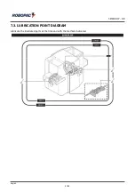
Страница 81: ...SPIROR HP DR 7 3 LUBRICATION POINT DIAGRAM Lubricate the illustrated parts at the time and with the methods indicated English 81 95 ...

Страница 82: ...ubricants oils or grease recommended by the manufacturer or with similar chemical physical features 7 4 LUBRICANTS TABLE Oil and grease table Type of lubricant Name Parts to be lubricated Mineral oil 23 C 50 C 320 CST 40 C MELLANA OIL 320 IP SPARTAN EP 320 ESSO BLASIA 320 AGIP MOBILGEAR 632 MOBIL OMALA EP 320 SHELL ENERGOL GR XP 320 BP Gear motor English 82 95 ...

Страница 83: ...ain Synthetic oil 25 C 45 C VG 150 SAE 40 45 C 70 C VG 220 SAE 50 Table rotation chain Important Do not mix oils of different makes and specifications 7 5 DRAINING THE CONDENSATE Proceed as indicated 1 Close the tap A and control the level of condensation in the container B 2 Unscrew if necessary the valve C to empty condensation 3 Push the valve C up until all condensation is removed 4 Tighten th...

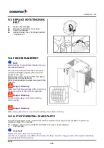
Страница 84: ...he tension of the belt by operating on the B nuts 3 Once adjustment has been performed tighten nut A 7 8 PRODUCT INFEED UNIT CHAIN ADJUSTMENT 1 Loosen nut A 2 Operate on the B tightening nuts until reaching the correct tension of the chain 3 Tighten the nut A English 84 95 ...

Страница 85: ... The chromed shafts must be cleaned with a cloth and slightly lubricated with a cloth soaked in Vaseline oil The parts in plastic material must be cleaned with a slightly damp cloth do not use alcohol petrol or solvents The control panel is only to be dusted with a dry cloth For the cleaning of the parts inside the machine consult our Technical Assistance Service personnel English 85 95 ...

Страница 86: ...ning time Wrapping terminates too far from the product edge increase the tail positioning time The wrapping laps are not compact Check if the spool has been mounted correctly according to the film s adhesive side 8 2 ALARM MESSAGES In the event of a breakdown during operations the machine stops automatically and alarm messages appear on the display The table lists the displayed messages the type o...

Страница 87: ...E SEALING Cause Rotating ring and sealing improperly timed Remedy If the units are in homing position check the sensors otherwise move them to Home position manually E42 ROTATING RING IMPROPERLY TIMED Cause Rotating ring improperly timed Remedy Check the rotation Home sensor E50 WARNING BUS CAN OPEN COMMUNICATION ALARM Cause The PLC can t gather information from the CAN OPEN hubs Remedy Check the ...

Страница 88: ... cylinders are malfunctioning Remedy Check and replace the sensor if necessary E66 WARNING UPPER CUT OFF NOT IN POSITION Cause Magnetic sensors of the upper cut off cylinder are malfunctioning Remedy Check and replace the sensor if necessary E67 BLADE NOT IN POSITION ALARM Cause Clamp cylinder magnetic sensors not properly working Remedy Check and replace the sensor if necessary E68 STOPPER NOT IN...

Страница 89: ...l and the personnel nearby In particular confine the neighbouring areas to impede access to the devices that could if activated produce unexpected danger conditions provoking hazards to personal safety and health When replacing worn parts use only original replacement parts The Manufacturer is not responsible for any damage to property or injuries to people caused by the use of non genuine spare p...

Страница 90: ...ng Make sure that the amperage of the new fuse is the same as that of the one to be replaced i Danger Warning Do not bring in water oil or dirt inside the electric panel i Danger Warning When closing the door be careful not to damage the cables and wiring 9 5 LIST OF ESSENTIAL SPARE PARTS List of the spare parts of easy wear and of which it would be necessary to have available to avoid long operat...

Страница 91: ...Useful information for the disposal of machines and machine parts Scrapping must be performed by qualified personnel Construction material Low density linear polyethylene L L D PE Steel aluminium and cast iron Copper and silver in the electrical electronic components Rubber resins and fibres None of the component materials is harmful or poisonous Special care must be taken when disposing of leftov...

Страница 92: ...sses due to lack of production or injuries to persons or damage to things caused by malfunctions or forced suspension in using the machine covered by the warranty THE WARRANTY DOES NOT COVER damage caused by transport damage due to incorrect installation improper use of the machine or negligence tampering or repairs by unauthorised personnel lack of maintenance parts subject to normal wear and tea...

Страница 93: ...A Air treatment unit B Solenoid valve C Presser drive pneumatic cylinder D Adjust Pressure units thrust manometer E Open close clamp pneumatic cylinder F Pneumatic cylinder forward clamp backward G Self centring guides pneumatic cylinder optional English 93 95 ...

Страница 94: ...A Air treatment unit B Solenoid valve C Presser drive pneumatic cylinder D Adjust Pressure units thrust manometer E Open close clamp pneumatic cylinder F Pneumatic cylinder forward clamp backward G Self centring guides pneumatic cylinder optional English 94 95 ...

Страница 95: ...IS IN CONFORMITY WITH DIRECTIVES DIRECTIVE 2006 42 EC OF THE EUROPEAN PARLIAMENT AND OF THE COUNCIL of 17 May 2006 on machinery and amending Directive 95 16 EC DIRECTIVE 2014 30 EU OF THE EUROPEAN PARLIAMENT AND OF THE COUNCIL of 26 February 2014 on the harmonisation of the laws of the Member States relating to electromagnetic compatibility Reference to harmonised standards and relevant annexes in...

Отзывы: