- It is not possible to start the machine when the spindle lock (fig 16 – 17) is functioning.
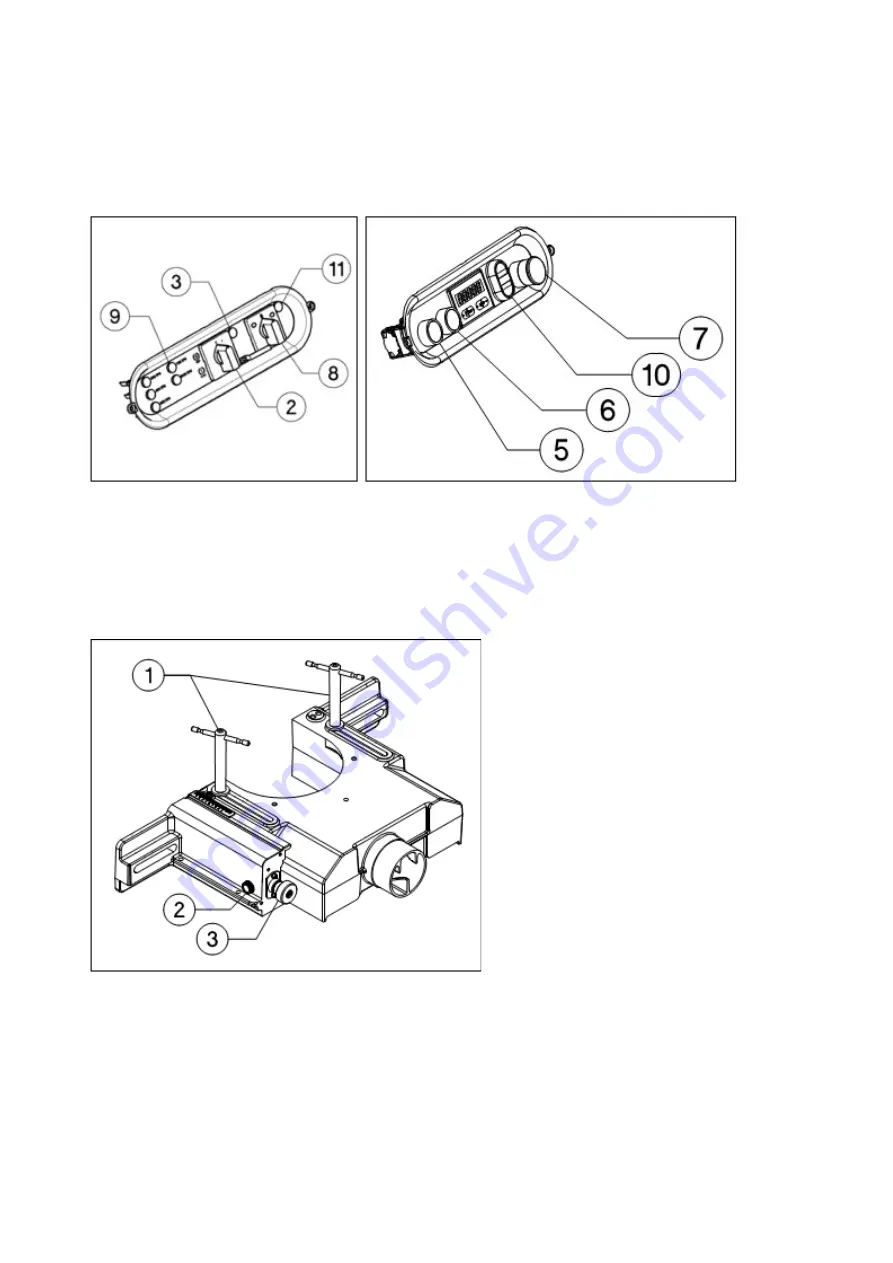
- The control lights (fig 6.9) indicate the speed of the spindle.
- The switch (fig 6.10) determines electric up or down movement of the spindle (option) and functions only
when the main motor is switched off.
- When using automatic star delta (fig 6.8) the direction of the rotation is determined by the switch.
- To prevent the machine from turning the wrong direction there is an additional security feature. Should the
machine turn in the opposite direction a yellow indicator lights up(fig 4.11 / fig 6.11).
Fig 6
Fig 7
Adjustment of the spindle fence (fig 8-9)
Basic version (fig 8)
- The body of the spindle fence is attached to the table with 2 bars (fig 8.1).
- The infeed fence can be arranged micrometric relative to the body of the fence by a knurled screw (fig 8.3).
- the position is locked by a knob (fig 8.2) on the side of the spindle fence.
Fig 8
Pro version
- The body of the spindle fence is located on a guide plate and moves on linear guides.
- This plate is attached to the table by 2 locking pins (fig 9.1).
- The spindle fence is moved by using a hand-wheel (fig 9.2).
- Use the other hand-wheel to control the infeed fence (fig 9.3).
- Use the locking screw (fig 9.4) to lock the infeed guide in position.
- The body of the spindle fence is attached to the table with a bar (fig 9.5).
15
Содержание T-120 L
Страница 1: ...1...
Страница 9: ...General dimensionsT 120 S L P 9...
Страница 26: ...26...
Страница 34: ...Algemeine AbmessungenT 120 S L P 34...


