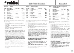
Baustufe 5:
Antrieb
Pos.-Nr.
Bezeichnung
Maße (mm)
Anzahl
5.1
Welle mit Zahnrad, Z66
1 n.e.
5.2
Getriebegehäuse
1 n.e.
5.3
Kupplung
1
5.4
Madenschraube
M3 x 3
2
5.5
Rückwand
1 n.e.
5.6
E-Motor
1 n.e.
5.7
Kondensator
100 nF
2 n.e.
5.8
Isolierschlauch
4 n.e.
5.9
Kondensator
47 nF
1 n.e.
5.10
Fahrtregler
1 n.e.
5.11
Zylinderschraube
mit Innensechskant
M3 x 10
2 n.e.
5.12
Kardanwelle
ø 5 x 132
1
5.13
Doppelklebeband
1 n.e.
Montage des Elektromotors und des Antriebsstrangs
(Pos. 5.1- 5.13)
-
Welle mit Zahnrad 5.1 in das Getriebegehäuse 5.2
einstecken.
-
Kupplung 5.3 mit Madenschrauben 5.4 am Wellenende
montieren.
-
Zahnrad mit Präzisionsfett leicht einfetten und
Rückwand 5.5 einsetzen.
-
Den Motor 5.6 entstören. Dazu die Kondensatoren 5.7
(100 nF) jeweils mit einem Beinchen an das Gehäuse
löten, welches dazu blankzufeilen ist. Zweites
Beinchen mit Isolierschlauch 5.8 an die Motorpole
stecken. Die Beinchen des Kondensators 5.9 (47 nF)
mit Isolierschlauch 5.8 versehen und ebenfalls an die
Motorpole stecken.
-
Das Motoranschlußkabel des Reglers 5.10 an die Mo-
torpole löten, die Kondensatoren werden dabei mitver-
lötet. Auf richtige Polarität achten. Regleranleitung
beachten.
-
Elektromotor 5.6 und Einheit 5.1 - 5.5 mit den
Innensechskant-Zylinderschrauben 5.11 am
Motorhalter 4.5 verschrauben, dabei die Kardanwelle
5.12 in die Kupplung 5.3 und die Antriebswelle 3.9 ein-
setzen.
-
Regler 5.10 mit Doppelklebeband 5.13 am Motor 5.6
befestigen.
Stage 5:
The power system
Part No.
Description
Size (mm)
No. off
5.1
Shaft and gear, 66-tooth
1 N.I.
5.2
Gearbox housing
1 N.I.
5.3
Coupling
1
5.4
Grubscrew
M3 x 3
2
5.5
Rear cover
1 N.I.
5.6
Electric motor
1 N.I.
5.7
Capacitor
100 nF
2 N.I.
5.8
Insulating sleeve
4 N.I.
5.9
Capacitor
47 nF
1 N.I.
5.10
Speed controller
1 N.I.
5.11
Socket-head cap screw
M3 x 10
2 N.I.
5.12
Propeller shaft
5 Ø x 132
1
5.13
Double-sided foam tape
1 N.I.
Assembling and installing the electric motor and power
train (parts 5.1 - 5.13)
-
Fit the shaft and gear 5.1 in the gearbox housing 5.2.
-
Fit the coupling 5.3 on the end of the shaft and fit the
grubscrews 5.4.
-
Lubricate the gear lightly with precision grease and fit
the rear cover 5.5.
-
The next step is to attach the suppressors to the termi-
nals of the motor 5.6: file two areas of the motor can
perfectly clean close to the terminals, and solder one
pin of each 100 nF capacitor 5.7 to those points. Slip a
piece of insulating sleeve 5.8 on the other pins, and
thread the ends through the motor terminals. Insulate
both pins of the 47 nF capacitor 5.9 and slip it through
both terminals to form a bridge.
-
Solder the power cables attached to the speed con-
troller 5.10 to the motor terminals, soldering the
capacitors in place at the same time. Take care to
maintain correct polarity, and read the instructions
supplied with the speed controller.
-
Fix the electric motor 5.6 and the assembly 5.1 - 5.5
to the motor mount 4.5 using the socket-head cap
screws 5.11.
-
At the same time slide the propeller shaft 5.12 into the
coupling 5.3 and the drive shaft 3.9.
-
Fix the speed controller 5.10 to the motor 5.6 using
double-sided foam tape 5.13.
Stade 5:
Montage du moteur électrique et de
l’entraînement
n°
désignation
cotes (mm)
nbre
5.1
arbre avec roue dentée, 66 dents
1 n.c.
5.2
carter d’engrenage
1 n.c.
5.3
accouplement
1
5.4
vis sans tête
M 3 x 3
2
5.5
paroi arrière
1 n.c.
5.6
moteur électrique
1 n.c.
5.7
condensateur
100 nF
2 n.c.
5.8
tube isolant
4 n.c.
5.9
condensateur
47 nF
1 n.c.
5.10
variateur
1 n.c.
5.11
vis à tête cylindrique
six pans creux
M 3 x 10
2
5.12
cardan
ø 5 x 132
1
5.13
adhésif double face
1 n.c.
Montage du moteur électrique et de l’entraînement
(n° 5.1 à 5.13)
-
Planter l’arbre avec la roue dentée 5.1 dans le carter
d’engrenage 5.2.
-
Monter l’accouplement 5.3 avec les vis sans tête 5.4
sur l’extrémité de l’arbre.
-
Graisser légèrement la roue dentée avec de la graisse
de précision et mettre la paroi arrière 5.5 en place.
-
Antiparasiter le moteur 5.6. Pour ce faire, souder
chaque fois une broche des condensateurs 5.7 (100
nF) au carter du moteur après en avoir poncé la sur-
face. Raccorder les autres extrémités aux pôles du
moteur en les engageant à laide d’un morceau de tube
isolant 5.8. Munir les broches du condensateur 5.9 (47
nF) de morceaux de tube isolant 5.8 et les raccorder
également aux pôles du moteur.
-
Souder cordon du moteur solidaire du variateur aux
pôles du moteur en soudant simultanément les
broches des condensateurs. Veiller à observer les
polarités. Tenir compte des indications fournies
par la notice du variateur.
-
Visser le moteur électrique 5.6 et l’unité 5.1 à 5.5 avec
les vis à tête cylindrique six pans creux 5.11 au sup-
port-moteur 4.5.
-
Ce faisant, engager le cardan 5.12 dans l’accouple-
ment 5.3 et l’arbre d’entraînement 3.9.
-
Fixer le variateur 5.10 avec de l’adhésif double face
5.13 au moteur 5.6.
MAN F2000
Evolution
Baustufe 5
17
Содержание MAN F2000 Evolution
Страница 10: ...MAN F2000 Evolution Baustufe 3 10 3 1 3 2 3 6 3 5 3 1 3 4 3 1 3 7 3 3 3 2 3 1 3 3...
Страница 20: ...MAN F2000 Evolution Baustufe 7 20 5 6 2 19 7 1 7 1 7 2 2 19 5 10 5 10...
Страница 22: ...MAN F2000 Evolution Baustufe 8 22 8 1 8 2 8 4 8 7 8 8 8 9 8 10 8 3 8 5 8 6 8 10 1 1...
Страница 30: ...MAN F2000 Evolution Baustufe 11 30 7 1 10 2 11 4 11c 11a 11b 11d 7 1 11 1 10 2 11 1 11 2 11 3 11 5...
Страница 42: ...42...


