


fluctuations, and suppress mains interference.
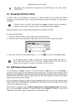
The inlets are labeled in the sequence they appear when looking from the front of the
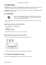
device. This helps identifying the active power source on the display.
The
power switch
next to the two inlets internally disconnects the line connection of the C14 inlets to the
power supplies. Ground and neutral will remain connected.
Lockable IEC plugs
The inlets can be used with special IEC power cords that have a lockable connector. Please contact a
local distributor to purchase these power cords if needed.
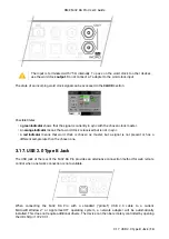
3.11. Analog Line Output Connectors
The rear of the M-32 DA Pro features 25-pin D-sub connectors labeled "LINE OUT" with Tascam®-pinout.
The short circuit protected, low impedance balanced line outputs at the D-Sub connectors
do not operate servo balanced. When connecting unbalanced equipment, make sure pin 3
("cold") of the output is not connected. A connection to ground may cause a decreased
THD (higher distortion) and increased power consumption!
3.12. Analog Line Levels
The M-32 DA Pro can be adjusted to the following reference levels:
Reference
0 dBFS
Headroom at
+4dBu
Other RME
devices
+24
+24 dBu
20 dB
-
RME M-32 DA Pro User’s Guide
3.11. Analog Line Output Connectors |
10


