background image

English

Translation of the original operating and assembly instructions

FGHJ INOX_Manual-en_R0

ID 76429

Operating and Assembly Instructions

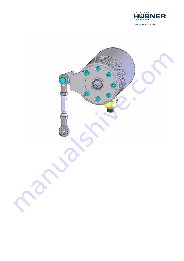
Incremental Hollow Shaft Encoder FGHJ INOX

Read the operating and assembly instructions prior to
assembly, starting installation and handling!
Keep for future reference!

Содержание FGHJ INOX

Страница 1: ...sembly instructions FGHJ INOX_Manual en_R0 ID 76429 Operating and Assembly Instructions Incremental Hollow Shaft Encoder FGHJ INOX Read the operating and assembly instructions prior to assembly starting installation and handling Keep for future reference ...

Страница 2: ...7969 0 Fax 49 641 73645 E Mail info huebner giessen com www huebner giessen com The manual has been drawn up with the utmost care and attention Nevertheless we cannot exclude the possibility of errors in form and content It is strictly forbidden to reproduce this publication or parts of this publication in any form or by any means without the prior written permission of Johannes Hubner Fabrik elek...

Страница 3: ...afeguarding against restart 8 3 Technical Data 9 3 1 Type plates 9 3 2 Electrical and mechanical data 10 3 3 Signal outputs 11 4 Overview additional options 11 4 1 Option S overspeed switch 11 4 2 Option LWL signal transmission using fiber optics 11 4 3 Type code 12 5 Transport packaging and storage 13 5 1 Safety instructions for transport 13 5 2 Incoming goods inspection 13 5 3 Packaging disposal...

Страница 4: ...n 20 7 2 Dismantling the encoder 20 8 Faults 21 8 1 Faults table 21 9 Inspections 22 9 1 Safety instructions 22 9 2 Maintenance information 22 9 3 Inspection schedule 22 10 Disposal 22 10 1 Disposal procedure 22 11 Replacement parts 22 12 Dimension drawings 23 13 connection diagrams 31 13 1 Terminal box 31 ...

Страница 5: ...rnings are introduced by signal words that express the scope of the hazard The warnings must be strictly heeded you must act prudently to prevent accidents personal injury and property damage WARNING Indicates a possibly dangerous situation that can result in death or serious injury if it is not avoided CAUTION Indicates a possibly dangerous situation that can result in minor injury if it is not a...

Страница 6: ...an in conjunction with using the device without the prior written agreement of the manufacturer Any copyright infringements will be prosecuted 1 6 Guarantee terms The guarantee terms are provided in the manufacturer s terms and conditions 1 7 Customer service For technical information personnel is available that can be contacted by telephone fax or email See manufacturer s address on page 2 2 Safe...

Страница 7: ...lyester Before use in corrosive atmospheres it is recommended to test the corrosion resistance Claims of any type due to damage arising from non intended use are excluded The owner bears sole responsibility for none intended use 2 4 Improper use Do not use the device in potentially explosive areas The device must not be subjected to mechanical loads in addition to its own weight and unavoidable vi...

Страница 8: ...aces WARNING Danger of injury due to rotating shafts and hot surfaces Touching rotating shafts can cause serious injuries Therefore Do not reach into moving parts shafts or handle moving parts shafts during operation Close to protect from injury all access openings in flanges with the corresponding plug screw and provided you exposed rotating components with protective covers Do not open covers du...

Страница 9: ...e plate is located on the outside of the housing and contains the following information Englisch Deutsch Manufacturer address Hersteller Anschrift Type Incremental Encoder Year of manufacture Typ Inkrementaler Drehgeber Baujahr CE mark CE Kennzeichnung Serial number S N Seriennummer S N Pulse rate Impulszahl Degree of protection Schutzart Supply voltage Versorgungsspannung Outputs Ausgänge ...

Страница 10: ...ulse height HTL approx as supply voltage Output current per output 150 mA peak Duty cycle 1 1 5 Square wave displacement 0 90 90 5 Max frequency 200 kHz Start up time 100 ms Encoder temperature range 25 C 85 C Degree of protection acc DIN EN 60529 Sealing Mech permissible speed Rotor moment of inertia Breakaway torque IP66 With radial shaft seal V4A housing 6000 rpm approx 315 gcm approx 3 5 4 Ncm...

Страница 11: ...s It is recommended to save the switch circuit against an overcurrent with a fuse 0 5A Specification Value Deviation from switch Accuracy of measurement 2 Switching time TSw 3ms Switch data 0 30V DC max 500mA Max voltage drop at closed switch 0 7V 4 2 Option LWL signal transmission using fiber optics The signals 0 90 and marker pulse from the incremental encoder will be encoded and transmitted via...

Страница 12: ...ons AK Terminal box AL Terminal box with connector for ST compatible fiber optic plug Pulses per rotation 1 2048 preset selectable Basic version Basic channel 0 A Pulse channel 90 B each with inverted signals not for LWL see chapter 4 2 NG Reference pulse with inverted signal S Option S Hollow shaft bore 16K cylindrical shaft with clamping 17C cone shaft 0 75 R with clamping ring 12K cylindrical s...

Страница 13: ...the forwarder directly on receipt of the goods about existing transport damages prepare pictures for evidence 5 3 Packaging disposal The packaging is not taken back and must be disposed of in accordance with the respective statutory regulations and local guidelines 5 4 Storage of packages devices Keep dry Keep packages dry and free from dust protect from moisture Protect against heat Protect packa...

Страница 14: ... length of the signal cable and the place of installation please refer to Chapter 3 2 Degree of protection To fulfill degree of protection requirements the diameter of the connection cable must correspond to that of the cable gland please refer to Chapter 12 Dimension drawings Deep groove ball bearings FGHJ INOX incremental hollow shaft encoders are fitted with maintenance free greased for life de...

Страница 15: ...sure all accessories are available please refer to Chapter 12 Dimension drawings NOTES Fastening screws and earth cable are not included in the range of supply 2 Preparing the place of attachment Clean the motor shaft centering bolting surfaces and fastening threads check for damage Repair any damage ...

Страница 16: ...y turning it counterclockwise The terminal box cover has a right hand thread 3 Slide the circular spring device 2 onto the adapter shaft until it stops 4 Mount the hollow shaft device 3 to the adapter shaft The hollow shaft encoder must slide smoothly on to the adapter shaft In no delay with increased force otherwise the bearing may be damaged Where appropriate adapter shaft with emery cloth rewor...

Страница 17: ...ink rod 6 to a fixed point for example on the motor housing NOTES Once fitted the link rod must rotate easily around the link rod heads Failure to observe this point may result in damage to the bearings NOTES The link heads are maintenance free However ensure they remain free from soiling and paint The torque arm can be screwed to the housing cover offset by 180 For this purpose the two fixing scr...

Страница 18: ... terminal box trough the cable gland NOTES The signal cable shielding has to be connected directly to the housing via the EMC cable gland To achieve an effective shielding the cable shield must also be connected in the electrical cabinet 4 Tighten the cable gland using a spanner NOTES Prior to delivery cable glands and blanking plugs are tightened finger tight only To ensure that the terminal box ...

Страница 19: ...l cable and possibly option S please refer to the connection diagrams Chapter 13 CAUTION Do not apply supply voltage to the signal outputs as this will destroy the device 7 Close the terminal box cover NOTES Before closing the terminal box cover check and if necessary clean both seal surfaces and the gasket ...

Страница 20: ...ammer or similar tool when dismantling the device due to the risk of damage occurring to the bearings or coupling 7 2 Dismantling the encoder Disconnect all electrical cable prior to beginning any work To dismantling the encoder follow the instructions given in Chapter 6 5 in the reverse order For dismounting first a threaded pin M6x10 ISO 7436 has to be screwed into the adapter shaft With a screw...

Страница 21: ...inal box gasket Cable gland blanking plug not tightened Tighten cable gland blanking plug Unsuitable cable for cable gland Use suitable cable and cable glands No output signals Supply voltage not connected Connect supply voltage Connection cable reversed Wire correctly Output signals subject to interference Unsuitable cable Use data cable with conductors arranged as twisted pairs and common shield...

Страница 22: ...nd connection terminals are securely seated Following approx 16 000 20 000 hours of operation higher levels of continuous load Check deep groove ball bearings are running smoothly and listen for running noises For FGHJ INOX with option S no extra inspection is required 10 Disposal 10 1 Disposal procedure The manufacturer is not obliged to take back the device The device must be treated as special ...

Страница 23: ...Incremental Hollow Shaft Encoder FGHJ INOX FGHJ INOX_Manual en_R0 23 12 Dimension drawings ...

Страница 24: ...Incremental Hollow Shaft Encoder FGHJ INOX 24 FGHJ INOX_Manual en_R0 ...

Страница 25: ...Incremental Hollow Shaft Encoder FGHJ INOX FGHJ INOX_Manual en_R0 25 ...

Страница 26: ...Incremental Hollow Shaft Encoder FGHJ INOX 26 FGHJ INOX_Manual en_R0 ...

Страница 27: ...Incremental Hollow Shaft Encoder FGHJ INOX FGHJ INOX_Manual en_R0 27 ...

Страница 28: ...Incremental Hollow Shaft Encoder FGHJ INOX 28 FGHJ INOX_Manual en_R0 ...

Страница 29: ...Incremental Hollow Shaft Encoder FGHJ INOX FGHJ INOX_Manual en_R0 29 ...

Страница 30: ...Incremental Hollow Shaft Encoder FGHJ INOX 30 FGHJ INOX_Manual en_R0 ...

Страница 31: ...llow Shaft Encoder FGHJ INOX FGHJ INOX_Manual en_R0 31 13 connection diagrams 13 1 Terminal box NOTES The connection diagrams are displayed in each terminal box cover Connection technology AK Connection technology AL ...

Отзывы: