Riverside Hydronics 1500 WB 250A-IF Скачать руководство пользователя страница 6

34-55   08/14


3 BOILER 

INSTALLATION 

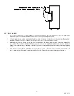
3.1  Checking Equipment Before You Install 


Inspect the unit completely upon receipt from the freight carrier before signing the bill of lading. Inspect the appliance 
and all accompanying parts for signs of impact or mishandling. Verify the total number of pieces shown on packing 
slips with those actually received. Contact the freight carrier immediately if any damage or shortage is detected. 

3.2 Codes


The equipment must be installed in accordance with those installation regulations in force in the local area where the 
installation is to be made. Authorities having jurisdiction must be consulted before installation is made. In the 
absence of such requirements, the installation must conform to the latest edition of the National Fuel Gas Code, 
ANSI Z223.1. Where required by the authority having jurisdiction, the installation must conform to American Society 
of Mechanical Engineers Safety Code for Controls and Safety Devices for Automatically Fired Boilers, No. (CSD-1). 
Where required by the Canadian authority having jurisdiction, the equipment must be installed in accordance with the 
latest edition of the Installation Code for Gas Burner Appliances and Equipment CAN/CSA B149 and/or B149.2 and 
applicable Provincial Regulations. All appliances conform to the latest edition of the ASME Boiler and Pressure 
Vessel Code, Section IV. 

3.3 Electrical Requirements


    See appliance rating decal for electrical service requirements. The appliance must be electrically supplied and 

grounded in accordance with the requirements of the authority having jurisdiction or in the absence of such 
requirements, with the latest edition of the National Electrical Code ANSI/NFPA No. 70. When the unit is installed in 
Canada, it must conform to the CSA C22.1, Canadian Electrical Code, Part 1 and/or Local Electrical Codes. 

  All wiring between the unit and field installed devices must be made with type T copper wire. 

  Line voltage wire exterior to the appliance must be enclosed in approved conduit or approved metal clad cable. 

  To avoid serious damage, 

DO NOT

 energize the unit until the system and appliance is full of water. 

3.4 Location 

These units are suitable for indoor installation only. 


The boiler may be installed on a 4 inch to 6 inch housekeeping pad. 


Locate the unit so that if water connections should leak, water damage will not occur. When such locations are 
unavoidable, install a suitable drain pan, and plumb pan to ensure adequate drainage in the event of a leak. 
Under no circumstances is the manufacturer responsible for water damage in connection with this unit, or any of 
its components. The manufacturer’s warranty does not cover water damage. 


Protect associated electrical components and electrical connections from water (dripping, spraying, rain, etc.) 
during appliance operation and service. 


Place the appliance on a level, non-combustible floor. Concrete over wood is not considered non-combustible. 


Do not install on carpet or other combustible floor coverings. If installation over a combustible floor is required, 
follow these guidelines: 

  Use a base of hollow clay tile or concrete blocks from 8" to 12" thick and extending 24" beyond the sides. 

  Place the blocks in line so that the holes line up horizontally to provide a clear passage through the blocks. 

  Install 1/2” fireproof millboard with a 20-gage sheet metal cover over the block base. 

  Center the unit on the base. Also follow this procedure if electrical conduit runs through the floor, and 

beneath the appliance. A field-installed base must meet all local fire and safety code requirements. 

3.5 Service 

Clearances 

Provide adequate clearances on all sides for installing and servicing connections such as water, gas, vent, 
combustion air duct, electrical, pump and other auxiliary equipment. At least 24” above the boiler is required for filter 
replacement and burner/gas control service. 
 

3.6  Clearances To Combustible Surfaces 

    Minimum 1” clearance must be provided from any vent surface to adjacent combustible material. The minimum 

clearances to unprotected combustible material are 24” be provided at the front, 8” be provided at the rear and 8” at 
top, left and right sides of the appliance. 

Содержание 1500 WB 250A-IF

Страница 1: ...LOW THE INFORMATION IN THIS MANUAL AND ALL OTHER PROVIDED INSTRUCTIONS LABELS AND MARKINGS BEFORE INSTALLING OPERATING OR SERVICING THIS UNIT TO THE INSTALLER After installation these instructions mus...

Страница 2: ...ection 5 6 Gas Train and Controls Certification 5 7 Gas Control Trains 6 Combustion and Ventilation Air 6 1 Equipment Located In Confined Spaces 6 2 Maximum Allowed Remote Combustion Air Inlet Length...

Страница 3: ...mpTrac 10 4 Boiler Management System BMS Remote Connections 10 5 Outdoor Reset 10 6 OnTrac Boiler Management System BMS 10 7 BAS Protocol Gateway 11 Sequence of Operation 12 Initial Startup 12 1 Initi...

Страница 4: ...ut the main gas supply valve to the appliance from a location safely away from the emergency Failure to follow these instructions can cause property damage personal injury and exposure to hazardous ma...

Страница 5: ...5 34 55 08 14 2 PRODUCT DESCRIPTION Component Controls and Connection Locations Locations May Vary...

Страница 6: ...be enclosed in approved conduit or approved metal clad cable To avoid serious damage DO NOT energize the unit until the system and appliance is full of water 3 4 Location These units are suitable for...

Страница 7: ...ow pumping systems on the boiler loop motorized isolation valves may be recommended Building flow may have to be limited to only the firing boilers during periods of low building heat demand to preven...

Страница 8: ...xchanger can cause a non warrantable failure 3 Make sure there are no system leaks DO NOT use petroleum based stop leak products All system leaks must be repaired The constant addition of make up wate...

Страница 9: ...aight Pipe to add the equivalent straight pipe for each elbow or tee to obtain the total distance from the meter Use this corrected total distance from the meter for determining the suggested pipe siz...

Страница 10: ...off device 6 A sediment trap drip leg MUST be provided in the inlet of the gas connection to the unit 7 The code compliant vent limiters are designed and must respond to pressure changes in the instal...

Страница 11: ...tion Codes or applicable provisions of the local building codes NOTE This unit may be installed with a remote air intake system which uses a make up air duct to draw combustion air directly from outdo...

Страница 12: ...remote combustion air vent termination to adequately protect the combustion air inlet from wind and weather A UL Listed air intake termination cap is available from Riverside Hydronics and may have s...

Страница 13: ...om the appliance vent connection to the vertical vent or stack that terminates outside and above the building roof must be made with listed Type B double wall or equivalent must be as direct as possib...

Страница 14: ...manufacturer of the listed Category III or IV venting system being installed Attach this adapter to the VT3 vent connection outlet following the instruction provided by the adapter s manufacturer Foll...

Страница 15: ...e cfm Max Vent Press W C 399 136 0 5 500 170 0 6 650 221 0 8 750 255 1 0 850 289 1 2 900 306 1 2 1000 340 1 3 7 3 2 Vertical or Horizontal Vent Termination 1 The vent terminal must have a minimum clea...

Страница 16: ...personal injury exposure to hazardous materials or death Conventional Venting Through the Wall Venting Combining Vents with a Draft Inducer 8 OPERATING AND SAFETY CONTROLS 8 1 Operating Temperature C...

Страница 17: ...expansion Contact a boiler or plumbing professional to resolve this situation Do not plug the relief valve 8 4 Electronic Low Water Cut Off Low Water Cut Off Operation When the water level is above th...

Страница 18: ...g Probe 1 This is used to regulate the temperature of the boiler 9 4 Control Buttons SET Displays and modifies the temperature set points In programming mode it selects a parameter or confirms an oper...

Страница 19: ...will hold at low fire until parameter St4 is reached causing burner to modulate higher or parameter St1 is reached causing the burner to shutoff St4 The Modulation Threshold This additional differenti...

Страница 20: ...int Push the SET key The upper display will show the St1 parameter name while the lower display will show its value Use the UP or DOWN key to cycle through the parameter names Push the SET key to modi...

Страница 21: ...ted or is reading correctly Outdoor reset disabled Warm weather shutdown disabled Check wiring and sensor Terminals 16 17 HA High temperature limit setpoint exceeded Buzzer sounds operation continues...

Страница 22: ...daisy chain arrangement 10 4 Making BMS BAS remote connections for analog and binary on off signals A terminal strip for the remote connection is located behind the hinged control panel at the top of...

Страница 23: ...adjusted upward by the amount of the rr1 value See Outdoor Reset Manual 34 400 6 for full description Factory Default Settings The values of the Outdoor Reset and Warm Weather Shutdown functions in th...

Страница 24: ...he Fenwal Flame Safeguard Control d 24v is applied to the TempTrac operating temperature control terminal L1 3 Call For Heat If the TempTrac operating control senses a call for heat condition a The Hi...

Страница 25: ...lay On Low Fire Hold Relay has timed out it energizes the Modulation Release Relay SPDT to enable the analog signal from the TempTrac to the VFD to regulate the speed of the blower a The TempTrac will...

Страница 26: ...Tools 12 2 Resources Product Installation Maintenance Manuals Start up Report with instructions Local State Federal Codes Toll Free 24 Hour Technical Support 1 800 433 5654 12 3 On Site Consideration...

Страница 27: ...ng the rocker switch on the front of the control enclosure assembly When the burner fails to light the flame control will lockout Start the burner in Low Fire Burner combustion must be optimized at bo...

Страница 28: ...in the flue vent approximately two feet from the appliance See Gas Train Illustration below for details With the burner firing and adjusted to low fire adjust the regulator screw clockwise to increas...

Страница 29: ...LATOR VALVE ORIFICE ADJUSTMENT Gas Train Illustration for Centauri Models 250 through 500 REGULATOR ADJUSTMENT HIGH GAS PRESSURE SWITCH DUAL SAFETY SHUTOFF VALVE LOW PRESSURE GAS SWITCH MANIFOLD PRESS...

Страница 30: ...for proper blower pressure setting adjust if required Air switch may be defective Blocked Filter Switch Check for 24V at the N C side of the blocked filter switch Replace filter or switch as required...

Страница 31: ...31 34 55 08 14 14 REPLACEMENT PARTS REPLACEMENT PARTS...

Страница 32: ...32 34 55 08 14 14 1 Control Panel...

Страница 33: ...316SS 1 EA 8 102163 PROBE THERMOSTAT DIXELL 18NB NTC 25FT NICKEL BRASS 1 EA 9 104195 PROBE THERMOSTAT DIXELL 18NB NTC 5FT NICKEL BRASS 1 EA 10 116458 RELAY SPST 30A 24V OMRON G7L 1A TUB J CB AC24 N O...

Страница 34: ...34 34 55 08 14 14 3 Burner Assembly...

Страница 35: ...163 ELL BLACK 90DEG 1 16 2 5973 NIPPLE BLACK 1 4 X 2 17 1 101216 SWITCH PRESSURE HGP G ANTUNES 8101111202 2 20 W 18 1 101201 SWITCH PRESSURE LGP G ANTUNES 8103116202 1 20 W 19 1 SEE BOM NIPPLE BLACK 1...

Страница 36: ...n or installer should use the procedures described in item 5 6 below 3 Any sign of soot on the heat exchanger or in the flue indicates the need for a combustion inspection Properly installed and adjus...

Страница 37: ...combustion and ventilation air is unobstructed to the appliance 10 When electrical controls are serviced or replaced refer to ELECTRICAL COMPONENT LOCATIONS for identification and location of compone...

Страница 38: ...detection system components c Check firing rate control d Check piping and wiring of all interlocks and shutoff valves e Inspect burner components f Check igniter g Test high and low gas pressure inte...

Страница 39: ...39 34 55 08 14 NOTES...

Страница 40: ...40 34 55 08 14 MODEL NUMBER SERIAL NUMBER INSTALLATION DATE Riverside Hydronics LLC 990 Haltom Road Ft Worth TX 76117 1 800 990 5918 www riversidehydronics com...

Отзывы: