


2
34-55 08/14
TABLE OF CONTENTS
1. Safety
Considerations
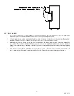
2. Product Description
3. Boiler
Installation
3.1.
Checking Equipment Before You Install
3.2. Codes
3.3. Electrical
Requirements
3.4. Location
3.5. Service
Clearances
3.6.
Clearances to Combustible Surfaces
4. General Piping Guidelines
4.1.
Inlet and Outlet Connections
4.2.
Supply and Return Piping
4.3.
Temperature Control Sensor (Install in system return piping)
4.4.
Filling the Boiler
5. Gas Supply Piping
5.1.
Inlet Gas Pressure
5.2.
Manifold Gas Pressure
5.3.
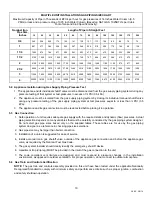
Gas piping Size
5.4.
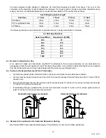
Appliance Isolation during Gas Supply Piping Pressure Test
5.5. Gas
Connection
5.6.
Gas Train and Controls Certification
5.7. Gas
Control
Trains
6. Combustion and Ventilation Air
6.1.
Equipment Located In Confined Spaces
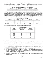
6.2.
Maximum Allowed Remote Combustion Air Inlet Length (Equivalent Length)
6.3.
Remote Combustion Air Cap
6.4.
Vertical or Horizontal Remote Air Duct Termination
6.5.
Remote Air Consideration for Combined Remote Air Ducting
7. Venting
7.1.
Venting the Unit Category I, III or IV Venting Materials
7.2.
Category I Venting
7.3.
Category III or IV Venting
7.3.1
Maximum Category III or Category IV Vent Length
7.3.2
Vertical or Horizontal Vent Termination
7.3.3
Combining Category III or Category IV Vents
8. Operating and Safety Controls
8.1. Operating
Temperature Control
8.2.
High Water Temperature Limit Control
8.3. Relief
Valve
8.4.
Electronic Low Water Cut-Off
Содержание 1500 WB 250A-IF
Страница 5: ...5 34 55 08 14 2 PRODUCT DESCRIPTION Component Controls and Connection Locations Locations May Vary...
Страница 31: ...31 34 55 08 14 14 REPLACEMENT PARTS REPLACEMENT PARTS...
Страница 32: ...32 34 55 08 14 14 1 Control Panel...
Страница 34: ...34 34 55 08 14 14 3 Burner Assembly...
Страница 39: ...39 34 55 08 14 NOTES...