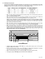
Riverside Hydronics 1500 WB 250A-IF Скачать руководство пользователя страница 20

20 

34-55   08/14


C to D: 

Once modulation is established, the sensed loop temperature can fluctuate 

between


155°F and 

145°F


(between St4 and SR). 

The firing rate increases or decreases proportionately between 100% and low 

fire, depending upon the temperature sensed in the return loop. Temperature rise in the heat exchanger 
varies accordingly, 45° to 15° depending upon the firing rate. 


D: 

The unit will remain in modulation until the sensed temperature rises above 

155°F (St4). 

The firing rate 

returns to low fire. Modulation will only reactivate when return loop temperature drops to 155°F. 


E to F: 

Low fire is maintained if the return loop temperature ranges between 

155° and 165°F

.  


F: 

This firing pattern will continue until the temperature reaches the “Burner OFF” threshold of 

165°F


(St1)


and shuts off

.


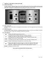
9.6  To View The Setpoint 


  Push and release the 

SET

 key to see the set point value. 

  To return to normal display, press 

SET + UP 

or wait 15 seconds without pressing any key. 

9.7  To Change The Setpoint 


 Push 

the 

SET

 key. The upper display will show the “St1” parameter name, while the lower display will show 

its value. 

 Use 

the 

UP 

or

 DOWN

 key to cycle through the parameter names. 

 Push 

the 

SET

 key to modify a parameter value. The value starts flashing in the lower display. 

  To change it push the 

UP 

or 

DOWN

 keys. Push the 

SET

 key again to confirm the value and pass to the 

setting of next set point. 

  Repeat the operations described at points 3, 4, 5.


To Exit: 

press 

SET + UP 

or wait 15 seconds without pressing any key.


NOTE: 

Each point has a time out of 15 seconds. If any key is pushed within 15 seconds the controller exits the 

set points programming procedure. 

NOTE

: The set value is stored even when the procedure is exited by waiting the time-out to expire. 

9.8  To Change Other Parameters


 Push 

the 

SET


and


DOWN

 arrow simultaneously for 3 seconds. 

  Select the required parameter. The name of the parameter is on the upper display; its value is on the lower 

display. 

 Press 

the 

SET

 key: the value of the parameter will start blinking. 

 Use 

UP

 or 

DOWN

 to change the value. 

 Press 

SET

 to store the new value and move to the following parameter. 


To Exit

: Press 

SET + UP 

or wait 15s without pressing a key. 

Содержание 1500 WB 250A-IF

Страница 1: ...LOW THE INFORMATION IN THIS MANUAL AND ALL OTHER PROVIDED INSTRUCTIONS LABELS AND MARKINGS BEFORE INSTALLING OPERATING OR SERVICING THIS UNIT TO THE INSTALLER After installation these instructions mus...

Страница 2: ...ection 5 6 Gas Train and Controls Certification 5 7 Gas Control Trains 6 Combustion and Ventilation Air 6 1 Equipment Located In Confined Spaces 6 2 Maximum Allowed Remote Combustion Air Inlet Length...

Страница 3: ...mpTrac 10 4 Boiler Management System BMS Remote Connections 10 5 Outdoor Reset 10 6 OnTrac Boiler Management System BMS 10 7 BAS Protocol Gateway 11 Sequence of Operation 12 Initial Startup 12 1 Initi...

Страница 4: ...ut the main gas supply valve to the appliance from a location safely away from the emergency Failure to follow these instructions can cause property damage personal injury and exposure to hazardous ma...

Страница 5: ...5 34 55 08 14 2 PRODUCT DESCRIPTION Component Controls and Connection Locations Locations May Vary...

Страница 6: ...be enclosed in approved conduit or approved metal clad cable To avoid serious damage DO NOT energize the unit until the system and appliance is full of water 3 4 Location These units are suitable for...

Страница 7: ...ow pumping systems on the boiler loop motorized isolation valves may be recommended Building flow may have to be limited to only the firing boilers during periods of low building heat demand to preven...

Страница 8: ...xchanger can cause a non warrantable failure 3 Make sure there are no system leaks DO NOT use petroleum based stop leak products All system leaks must be repaired The constant addition of make up wate...

Страница 9: ...aight Pipe to add the equivalent straight pipe for each elbow or tee to obtain the total distance from the meter Use this corrected total distance from the meter for determining the suggested pipe siz...

Страница 10: ...off device 6 A sediment trap drip leg MUST be provided in the inlet of the gas connection to the unit 7 The code compliant vent limiters are designed and must respond to pressure changes in the instal...

Страница 11: ...tion Codes or applicable provisions of the local building codes NOTE This unit may be installed with a remote air intake system which uses a make up air duct to draw combustion air directly from outdo...

Страница 12: ...remote combustion air vent termination to adequately protect the combustion air inlet from wind and weather A UL Listed air intake termination cap is available from Riverside Hydronics and may have s...

Страница 13: ...om the appliance vent connection to the vertical vent or stack that terminates outside and above the building roof must be made with listed Type B double wall or equivalent must be as direct as possib...

Страница 14: ...manufacturer of the listed Category III or IV venting system being installed Attach this adapter to the VT3 vent connection outlet following the instruction provided by the adapter s manufacturer Foll...

Страница 15: ...e cfm Max Vent Press W C 399 136 0 5 500 170 0 6 650 221 0 8 750 255 1 0 850 289 1 2 900 306 1 2 1000 340 1 3 7 3 2 Vertical or Horizontal Vent Termination 1 The vent terminal must have a minimum clea...

Страница 16: ...personal injury exposure to hazardous materials or death Conventional Venting Through the Wall Venting Combining Vents with a Draft Inducer 8 OPERATING AND SAFETY CONTROLS 8 1 Operating Temperature C...

Страница 17: ...expansion Contact a boiler or plumbing professional to resolve this situation Do not plug the relief valve 8 4 Electronic Low Water Cut Off Low Water Cut Off Operation When the water level is above th...

Страница 18: ...g Probe 1 This is used to regulate the temperature of the boiler 9 4 Control Buttons SET Displays and modifies the temperature set points In programming mode it selects a parameter or confirms an oper...

Страница 19: ...will hold at low fire until parameter St4 is reached causing burner to modulate higher or parameter St1 is reached causing the burner to shutoff St4 The Modulation Threshold This additional differenti...

Страница 20: ...int Push the SET key The upper display will show the St1 parameter name while the lower display will show its value Use the UP or DOWN key to cycle through the parameter names Push the SET key to modi...

Страница 21: ...ted or is reading correctly Outdoor reset disabled Warm weather shutdown disabled Check wiring and sensor Terminals 16 17 HA High temperature limit setpoint exceeded Buzzer sounds operation continues...

Страница 22: ...daisy chain arrangement 10 4 Making BMS BAS remote connections for analog and binary on off signals A terminal strip for the remote connection is located behind the hinged control panel at the top of...

Страница 23: ...adjusted upward by the amount of the rr1 value See Outdoor Reset Manual 34 400 6 for full description Factory Default Settings The values of the Outdoor Reset and Warm Weather Shutdown functions in th...

Страница 24: ...he Fenwal Flame Safeguard Control d 24v is applied to the TempTrac operating temperature control terminal L1 3 Call For Heat If the TempTrac operating control senses a call for heat condition a The Hi...

Страница 25: ...lay On Low Fire Hold Relay has timed out it energizes the Modulation Release Relay SPDT to enable the analog signal from the TempTrac to the VFD to regulate the speed of the blower a The TempTrac will...

Страница 26: ...Tools 12 2 Resources Product Installation Maintenance Manuals Start up Report with instructions Local State Federal Codes Toll Free 24 Hour Technical Support 1 800 433 5654 12 3 On Site Consideration...

Страница 27: ...ng the rocker switch on the front of the control enclosure assembly When the burner fails to light the flame control will lockout Start the burner in Low Fire Burner combustion must be optimized at bo...

Страница 28: ...in the flue vent approximately two feet from the appliance See Gas Train Illustration below for details With the burner firing and adjusted to low fire adjust the regulator screw clockwise to increas...

Страница 29: ...LATOR VALVE ORIFICE ADJUSTMENT Gas Train Illustration for Centauri Models 250 through 500 REGULATOR ADJUSTMENT HIGH GAS PRESSURE SWITCH DUAL SAFETY SHUTOFF VALVE LOW PRESSURE GAS SWITCH MANIFOLD PRESS...

Страница 30: ...for proper blower pressure setting adjust if required Air switch may be defective Blocked Filter Switch Check for 24V at the N C side of the blocked filter switch Replace filter or switch as required...

Страница 31: ...31 34 55 08 14 14 REPLACEMENT PARTS REPLACEMENT PARTS...

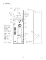
Страница 32: ...32 34 55 08 14 14 1 Control Panel...

Страница 33: ...316SS 1 EA 8 102163 PROBE THERMOSTAT DIXELL 18NB NTC 25FT NICKEL BRASS 1 EA 9 104195 PROBE THERMOSTAT DIXELL 18NB NTC 5FT NICKEL BRASS 1 EA 10 116458 RELAY SPST 30A 24V OMRON G7L 1A TUB J CB AC24 N O...

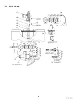
Страница 34: ...34 34 55 08 14 14 3 Burner Assembly...

Страница 35: ...163 ELL BLACK 90DEG 1 16 2 5973 NIPPLE BLACK 1 4 X 2 17 1 101216 SWITCH PRESSURE HGP G ANTUNES 8101111202 2 20 W 18 1 101201 SWITCH PRESSURE LGP G ANTUNES 8103116202 1 20 W 19 1 SEE BOM NIPPLE BLACK 1...

Страница 36: ...n or installer should use the procedures described in item 5 6 below 3 Any sign of soot on the heat exchanger or in the flue indicates the need for a combustion inspection Properly installed and adjus...

Страница 37: ...combustion and ventilation air is unobstructed to the appliance 10 When electrical controls are serviced or replaced refer to ELECTRICAL COMPONENT LOCATIONS for identification and location of compone...

Страница 38: ...detection system components c Check firing rate control d Check piping and wiring of all interlocks and shutoff valves e Inspect burner components f Check igniter g Test high and low gas pressure inte...

Страница 39: ...39 34 55 08 14 NOTES...

Страница 40: ...40 34 55 08 14 MODEL NUMBER SERIAL NUMBER INSTALLATION DATE Riverside Hydronics LLC 990 Haltom Road Ft Worth TX 76117 1 800 990 5918 www riversidehydronics com...

Отзывы: