


25
34-55 08/14
a.
The Delay-On (Low Fire Hold) Relay and the Gas Safety Valves are energized.
b.
During TFI the flame safeguard control will monitor the flame using flame rectification through the hot
surface igniter.
c.
If the flame control senses the presence of flame before the end of the TFI period, the igniter will be de-
energized and the flame control will continue to monitor the flame, through the igniter, until the operating
thermostat ends the call for heat condition.
7. Loss of Flame Signal
a.
If the igniter fails to sense flame at any time, the igniter and gas valve will be de-energized and the flame
control will reset and begin the call-for-heat sequence again. This will occur 3 times (one time if CSD-1)
before the flame control will lockout.
b.
When the call for heat condition ends or flame failure occurs following the third TFI period (one time if
CSD-1), a 30-second post-purge period will begin. This period of blower operation will exhaust any
remaining combustion products from the system.
8. Delay-On Relay
- Once the Delay-On (Low Fire Hold) Relay has timed out, it energizes the Modulation Release
Relay (SPDT) to enable the analog signal from the TempTrac to the VFD to regulate the speed of the blower.
a. The TempTrac will continue to monitor the stored water temperature in the tank.
b. When the setpoint temperature is reached the call-for-heat signal to the flame safeguard control is
discontinued.
c. The flame safeguard control deenergizes the VFD blower system and the gas valve, thereby suspending
burner operation.
d. As heat is transferred to the building, the boiler loop temperature will fall below the set point. The TempTrac
will sense this condition and begin the call-for-heat sequence again.
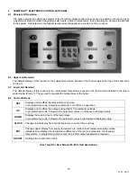
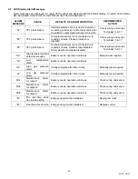
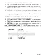
9. Flame Safeguard LED Diagnostic Indicator
- If the Fenwal Flame Safeguard Control at any time during the
operating sequence senses an improper operating state and locks out, the diagnostic red LED located on the
control board will flash to indicate one of the following conditions exist:
LED INDICATION
FAULT MODE
On
Normal Operation
OFF
Internal Control Failure – check power
1 Flash
Airflow Fault
2 Flashes
Erroneous Flame Signal
3 Flashes
Ignition Lockout
4 Flashes
Hot Surface Igniter Fault
5 Flashes
Low Voltage (24 VAC)
6 Flashes
Valve Relay Problem
Содержание 1500 WB 250A-IF
Страница 5: ...5 34 55 08 14 2 PRODUCT DESCRIPTION Component Controls and Connection Locations Locations May Vary...
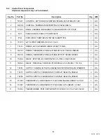
Страница 31: ...31 34 55 08 14 14 REPLACEMENT PARTS REPLACEMENT PARTS...
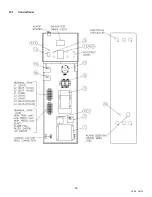
Страница 32: ...32 34 55 08 14 14 1 Control Panel...
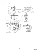
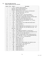
Страница 34: ...34 34 55 08 14 14 3 Burner Assembly...
Страница 39: ...39 34 55 08 14 NOTES...