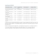
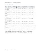
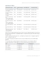
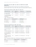
background image

Installing Network Cards in xx80 Appliances 


| 19

 3

Installing Network Cards in xx80 
Appliances

This chapter describes how to install network add-on cards (that is, network interface cards [NICs], and 
Peripheral Component Interconnect Express [PCIe] expansion and storage cards) in 1U and 2U xx80 
appliances. It includes these sections:

“1U xx80 appliances included in this chapter” on page 19

“2U xx80 appliances included in this chapter” on page 19

“Before you begin” on page 20

“Supported network add-on cards for SteelHead CX xx80 appliances” on page 20

“Supported network add-on cards for SteelCentral xx80 appliances” on page 24

“Maximum network cards and slot restrictions for SteelHead CX3080, CX5080, and CX7080 
appliances” on page 25

“Installing network add-on cards in 1U xx80 appliances” on page 26

“Installing network add-on cards in 2U SteelHead and SteelCentral xx80 appliances” on page 38

“Identifying interface names” on page 48

This chapter assumes you have installed and configured the appliance. For details, see the installation 
and configuration guide for your product.

1U xx80 appliances included in this chapter

This chapter describes how to install network cards in the these 1U appliances:

SteelHead CX3080

SteelCentral AppResponse 2180

SteelCentral Flow Gateway 2280

SteelCentral NetProfiler 4280-DP

2U xx80 appliances included in this chapter

This chapter describes how to install network cards in the these 2U appliances:

SteelHead CX5080 and CX7080

SteelCentral AppResponse 4180 and 8180

Содержание SteelCentral AppResponse 2170

Страница 1: ...d SD 3070 SD SteelHead Interceptor 9600 SteelCentral AppResponse 2180 4180 8180 2170 4170 6170 8170 SteelCentral Flow Gateway 2280 SteelCentral NetExpress 470 SteelCentral NetProfiler 4280 4280 DP 4280 EXP 2270 4270 EXP 4270 AN SteelCentral NetShark 2170 4170 6170 SteelFusion Core 3500 June 2020 ...

Страница 2: ... trademarks of VMware Inc in the United States and in other countries This product includes Windows Azure Linux Agent developed by the Microsoft Corporation http www microsoft com Copyright 2017 Microsoft Corporation This product includes software developed by the University of California Berkeley and its contributors EMC and Comtech AHA Corporation This product is derived from the RSA Data Securi...

Страница 3: ... 14 Troubleshooting 15 2 Fail to Block Mode 17 Overview 17 SteelHead GX CX EX DX Interceptor and SteelFusion NICs and fail to block functionality 18 SteelHead xx50 NICs and fail to block functionality 18 Fail to block CLI commands 18 3 Installing Network Cards in xx80 Appliances 19 1U xx80 appliances included in this chapter 19 2U xx80 appliances included in this chapter 19 Before you begin 20 Sup...

Страница 4: ... 41 Installing QAT Compression Acceleration cards in CX7080 B030 appliances 46 Identifying interface names 48 4 Installing Network Cards in SteelHead GX and xx70 SteelHead SD SteelCentral Interceptor 9600 and SteelFusion Core 3500 49 1U appliances included in this chapter 49 2U appliances included in this chapter 50 Before you begin 50 Supported cards for SteelHead GX SteelHead CX xx70 SteelHead S...

Страница 5: ...aces 92 6 Installing NICs for SteelHead Virtual Edition Appliances 95 Before you begin 95 Supported NICs for SteelHead v 96 Software compatibility 96 Supported cards 96 Identifying interface names in SteelHead v 97 Configuring bypass cards in ESXi 5 x 97 Configuring bypass cards for KVM 100 Before you begin 100 Changing the interface numbering with a custom XML file 101 Configuring bypass cards fo...

Страница 6: ... GbE Copper card 132 Four Port 10 GbE Copper card 133 Four Port 1 GbE Fiber Copper SFP card 134 Two Port 4 8 16 GbE FC HBA SAN 135 Two Port 10 GbE Fiber SFP card 135 Four Port 10 GbE Fiber SFP card 136 Two Port 40 GbE Time Stamp card 137 Four Port 10 GbE Fiber SR card 139 Four Port 10 GbE Fiber LR card 140 Four Port 10 GbE DAC redirector card 141 Four Port 10 GbE Copper card 141 C NIC Status Light...

Страница 7: ...rs 154 Series xx50 onboard copper GbE Ethernet ports 154 Series 150 250 and 550 154 Interceptor 9350 155 Two Port SX Multimode Fiber Gigabit Ethernet PCIe card 156 Four Port SX Multimode Fiber Gigabit Ethernet PCIe card 157 Four Port TX Copper Gigabit Ethernet PCIe card 159 Two Port LX Single Mode Fiber Gigabit Ethernet PCIe card 161 Four Port LX Single Mode Fiber Gigabit Ethernet PCIe card 161 Tw...

Страница 8: ...8 Contents ...

Страница 9: ...elCentral Controller for SteelHead SteelCentral Controller for SteelHead Mobile SteelCentral AppResponse SteelCentral Flow Gateway SteelCentral NetExpress SteelCentral NetProfiler SteelCentral NetShark SteelFusion Core NIC naming conventions Network interface cards described in this guide use the following abbreviations to indicate the type of card TX Copper Gigabit Ethernet GbE LX Single Mode Fib...

Страница 10: ...packaging until you are ready to install it Don t touch the electronic components on the NIC Safety guidelines Follow the safety precautions outlined in the Safety and Compliance Guide when installing and setting up your equipment Caution Failure to follow these safety guidelines can result in injury or damage to the equipment Mishandling of the equipment voids all warranties Read and follow safet...

Страница 11: ...ct Riverbed Support or your channel partner who provides support To contact Riverbed Support open a trouble ticket by calling 1 888 RVBD TAC 1 888 782 3822 in the United States and Canada or 1 415 247 7381 outside the United States You can also go to https support riverbed com Professional services Need help with planning a migration or implementing a custom design solution Contact Riverbed Profes...

Страница 12: ...12 Welcome Contacting Riverbed Documentation Have suggestions about Riverbed s online documentation or printed materials Send comments to techpubs riverbed com ...

Страница 13: ...n your network For SteelHead appliances the network card can prevent a single point of failure If there s a serious problem with an appliance the card goes into bypass mode and the traffic passes through unoptimized In addition some products and cards support fail to block mode where in the event of a failure traffic is re routed through a router or switch to an optimized backup path For details o...

Страница 14: ... configuration 1000 Base SX and 1000 Base LX interface options aren t available for the SteelHead 150 250 and 550 appliances The appliance supports VLAN Tagging IEEE 802 3 2008 It doesn t support the ISL protocol All copper interfaces are autosensing for speed and duplex IEEE 802 3 2008 The appliance autonegotiates speed and duplex mode for all data rates and supports full duplex mode and flow con...

Страница 15: ...128 255 This ping command creates a loop for testing the SteelHead in isolation For details on NIC status lights see the appendixes in this guide Troubleshooting The following diagnostic tips address common fixable issues Unseated card Sometimes cards can become unseated during shipment This can lead to system malfunctions including system reboots To correct this situation power down the system an...

Страница 16: ...16 Getting Started Troubleshooting ...

Страница 17: ...e without optimization With fail to block mode enabled in a redundant network path environment traffic is blocked and rerouted to an optimized backup path in the event of a failure This feature is useful only if the network has a routing or switching infrastructure that can automatically divert traffic from the link to the optimized backup path In an active backup redundant network setup the activ...

Страница 18: ...mands no interface interface name fail to bypass enable Sets the interface to block when there s a failure interface interface name fail to bypass enable Sets the interface to bypass when there s a failure For details on how to test a NIC see NIC self test for SteelHead on page 14 NIC description Manufacturing part Two Port SX Multimode Fiber GbE PCIe card 410 00101 01 Four Port SX Multimode Fiber...

Страница 19: ...lot restrictions for SteelHead CX3080 CX5080 and CX7080 appliances on page 25 Installing network add on cards in 1U xx80 appliances on page 26 Installing network add on cards in 2U SteelHead and SteelCentral xx80 appliances on page 38 Identifying interface names on page 48 This chapter assumes you have installed and configured the appliance For details see the installation and configuration guide ...

Страница 20: ...ctronic components on the network add on card Before you install a network add on card ensure the card meets the software and appliance requirements described in the following sections Supported network add on cards for SteelHead CX xx80 appliances This section describes the software requirements and network add on cards that you can install on SteelHead CX xx80appliances All the NICs for the Stee...

Страница 21: ...ent manufacturing location The 410 00115 11 card is the same card as the 410 00115 01 card Network add on cards Size Manufacturing part Orderable part Required software Four Port 10 GbE Fiber SR redirector FH7 6 410 00191 01 NIC 1 010G 4SR BP RiOS 9 9 1 or later Four Port 10 GbE Fiber LR redirector FH7 6 410 00190 01 NIC 1 010G 4LR BP RiOS 9 9 1 or later Four Port 10 GbE DAC redirector FH7 6 410 0...

Страница 22: ...s the 410 00115 01 card Network add on cards Size Manufacturing part Orderable part Required software Four Port 1 GbE Copper Base T Bypass HHHL 410 00115 01 NIC 1 001G 4TX BP RiOS 9 9 or later Four Port 1 GbE Fiber SX Bypass FHHL 410 00122 01 NIC 1 001G 4SX BP RiOS 9 9 or later Four Port 1 GbE Fiber LX Bypass FHHL 410 00123 01 NIC 1 001G 4LX BP RiOS 9 9 or later Four Port 10 GbE Fiber SR Bypass fi...

Страница 23: ...red software Four Port 1 GbE Copper Base T Bypass HHHL 410 00115 01 NIC 1 001G 4TX BP RiOS 9 9 or later Four Port 1 GbE Fiber SX Bypass FHHL 410 00122 01 NIC 1 001G 4SX BP RiOS 9 9 or later Four Port 1 GbE Fiber LX Bypass FHHL 410 00123 01 NIC 1 001G 4LX BP RiOS 9 9 or later Four Port 10 GbE Fiber SR field mountable spares only shipped separately FH7 6 410 00191 01 NIC 1 010G 4SR BP RiOS 9 9 or la...

Страница 24: ...nel HBA SAN 4280 4280 EXP only HHHL 410 00158 01 NIC 1 HBA 2FC 10 16 or later SFP Manufacturing part Orderable part SFP 10 GbE SR 410 00143 01 TRC 1 SFPP SR SFP 10 GbE LR 410 00144 01 TRC 1 SFPP LR SFP 10 GbE DAC 410 00142 01 TRC 1 SFPP DAC Network add on cards Size Manufacturing part Orderable part Required software Four Port 1 GbE Fiber SFP HHHL 410 00124 01 NIC 1 001G 4SFP 11 6 5 or later Four ...

Страница 25: ... SR4 QSFP 100 GbE LR4 410 00243 01 TRC 1 QSFP28 LR4 QSFP 40 GbE LM4 410 00245 01 TRC 1 QSFP LM4 Network add on cards Size Manufacturing part Orderable part Required software Two Port 10 GbE Fiber SFP HHHL 410 00036 02 NIC 1 010G 2SFPP 10 16 or later SFP Manufacturing part Orderable part SFP 10 GbE SR 410 00143 01 TRC 1 SFPP SR SFP 10 GbE LR 410 00144 01 TRC 1 SFPP LR SFP 10 GbE DAC 410 00142 01 TR...

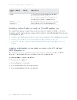
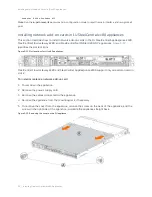
Страница 26: ... page 37 Installing and replacing network add on cards in the 1U SteelHead CX3080 appliances This section describes how to install or replace network add on cards in 1U SteelHead CX3080 appliances The network add on slot is located on the front of the appliance To install or replace a network add on card 1 Power down the appliance 2 Remove the power supply cord 3 Remove the cables connected to the...

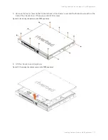
Страница 27: ...Remove the four screws on the front and back of the chassis cover and the three screws each on the side of the chassis cover There are a total of 14 screws Figure 3 1 Removing the screws on the 3080 appliance 6 Lift the chassis cover straight up Figure 3 2 Removing the chassis cover on the 3080 appliance ...

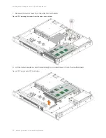
Страница 28: ... on cards in 1U xx80 appliances 7 Remove the two screws from the add on card holder Figure 3 3 Removing the screws from the add on card holder 8 Lift the network add on card holder straight up to disconnect it from the motherboard Figure 3 4 Removing the NIC card holder ...

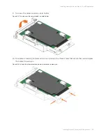
Страница 29: ...iances 9 Turn over the network add on card holder Figure 3 5 Turning over the network add on card holder 10 To replace an existing network add on card loosen the three screws that secure the card and press the bracket toward you Figure 3 6 Loosen the three screws and press the bracket toward you ...

Страница 30: ... 11 Slide the network add on card out of the pin connector and gently lift and pull the card away from the front of the card holder to remove it Figure 3 7 Removing the card from the pin connector 12 Hold the new network add on card between the front bezel and the rear of the card to avoid ESD damage ...

Страница 31: ...twork add on card 14 Screw the faceplate into the holder to secure the add on card Figure 3 9 Securing the faceplate Note Make sure the network add on card is seated properly in the pin connector If it isn t seated properly the card won t function properly 15 Press the bracket on the right side of the card holder toward you to position the card in the holder 16 Turn the card holder over ...

Страница 32: ...stalling network add on cards in 1U xx80 appliances 17 Press the card cover straight down into the motherboard pin connector Make sure the card is completely inserted into the motherboard Figure 3 10 Inserting the PCIe card holder into the motherboard ...

Страница 33: ... check the status lights For details on the status lights see Appendix A Network Card Status Lights for SteelHead and SteelCentral xx80 Appliances To test SteelHead network add on cards 1 Connect to the SteelHead CLI For detailed information see the Riverbed Command Line Interface Reference Manual 2 Enter enable mode At the system prompt enter the following command amnesiac enable amnesiac 3 Verif...

Страница 34: ...NetProfiler 4280 DP appliances Figure 3 12 identifies the slot locations Figure 3 12 Slot locations for 1U xx80 appliances SteelCentral Flow Gateway 2280 and SteelCentral AppResponse 2180 support only one add on card in slot 2 To install or replace a network add on card 1 Power down the appliance 2 Remove the power supply cord 3 Remove the cables connected to the appliance 4 Remove the appliance f...

Страница 35: ...ard bracket 7 Lift up to remove the riser card bracket from the chassis 8 If you are replacing an existing card carefully remove the screw and pull the card from the riser 9 Turn over the riser bracket unscrew the PCI dummy bracket and slide the bracket out Figure 3 15 Removing the dummy bracket 10 Hold the new card between the front bezel and the rear of the card to avoid ESD damage ...

Страница 36: ...te Make sure the cards are seated properly in the enclosure If they aren t seated properly the cards don t function 12 Turn over the riser card bracket see Figure 3 17 letter A press straight down to insert it and secure the two screws Figure 3 17 Inserting the riser card bracket into the chassis 13 Replace the cover on the chassis see Figure 3 13 Note Do not secure the rear side screw it will pre...

Страница 37: ... GbE NIC and racked the appliance power it on For details on installing NICs see Installing network add on cards in 1U SteelCentral xx80 appliances on page 34 2 Connect to the appliance using the console port Since you are modifying the appliance interfaces we recommend you connect via the console port rather than SSH 3 Log in to the appliance as user mazu password password set for the device 4 To...

Страница 38: ...0 slot restrictions on page 41 Installing network add on cards in 2U xx80 appliances on page 41 Installing QAT Compression Acceleration cards in CX7080 B030 appliances on page 46 2U xx80 slot locations and port numbering Figure 3 18 identifies the card slot locations for the 2U appliances The SteelCentral appliance is shown with the SSDs installed on the rear of the appliance Figure 3 18 Slot loca...

Страница 39: ...width Height Length Notes Slot 1 x8 FH Full Height FL Full Length When a x16 card is in slot 2 slot 1 can t be used Slot 2 x16 or x8 FH Full Height FL Full Length When a x16 card is in slot 2 slot 1 can t be used Two Port 40 GbE Fiber SR LR cards are only supported in slot 2 and 4 due to their larger size Slot 3 x8 FH Full Height HL Half Length 6 6 in SteelHead CX5080 and CX7080 appliances ship wi...

Страница 40: ...5 can t be used Slot 6 x8 See notes HL Half Length 6 6 in Full Height When a mezzanine card isn t installed Half Height CX7080 ships with a 3008 8i HBA mezzanine card preinstalled The CX7080 requires the 3008 8i HBA mezzanine card for internal PCIe and IO expansion The CX5080 doesn t require a mezzanine card Note The QAT Compression Acceleration card can be installed in the CX7080 B030 in slot 6 T...

Страница 41: ...crew on the top of the appliance see Figure 3 22 letter A SteelCentral product Slot restrictions SteelCentral AppResponse 4180 Only install NICs in slots 2 and 3 populating slot 2 first The appliance is equipped with preinstalled RAID cards Do not move or remove the RAID cards located in slots 4 5 and 6 SteelCentral AppResponse 8180 You can install 1 GbE and 10 GbE NICs in slots 2 and 3 populating...

Страница 42: ...x80 appliances 6 To remove the cover press the recessed tabs and push straight back see Figure 3 22 letter B Figure 3 22 Removing the cover on the 2U appliance 7 Remove the two screws on the back of the appliance see Figure 3 23 letter A and the two screws on the top of the riser brackets see Figure 3 23 letter B ...

Страница 43: ...pliances 43 Installing network add on cards in 2U SteelHead and SteelCentral xx80 appliances 8 Lift straight up to remove the riser cards from the chassis see Figure 3 23 letter C Figure 3 23 Lifting the riser brackets out of the chassis ...

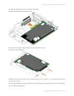
Страница 44: ...ee Figure 3 24 letter A and then remove it from the riser card bracket see Figure 3 24 letter B Figure 3 24 Removing the dummy bracket 10 Hold the new card between the front bezel and the rear of the card to avoid ESD damage 11 Align and insert the add on card into the riser connector see Figure 3 25 letter A and secure with a screw see Figure 3 25 letter B Figure 3 25 Installing the PCI riser ass...

Страница 45: ... two screws on the back of the appliance see Figure 3 26 letter B 14 Replace the cover on the chassis see Figure 3 22 15 Connect the cables Note For appliances with storage units attached that is the SteelCentral AppResponse 8180 reconnect the SAS cables to the same RAID cards prior to replacement 16 Connect the power cords 17 Power up the appliance and check the status lights To verify SteelHead ...

Страница 46: ... BIOS and BMC on the CX7080 B030 1 Upgrade your SteelHead CX7080 B030 appliance to RiOS 9 9 2 For details see the SteelHead Installation and Configuration Guide 2 Connect to the SteelHead CLI in configuration mode For details see Riverbed Command Line Interface Reference Manual 3 Run the following commands hidden mode hardware enable rfut reload The RFUT utility reloads the appliance upgrades the ...

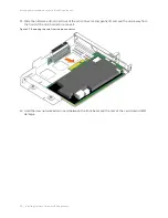
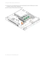
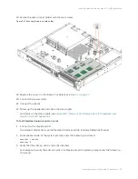
Страница 47: ...ard in slot 6 8 Reinstall the riser back to the unit and secure all the screws For details see Step 12 9 Install the cover and secure all the screws For details see Step 5 Figure 3 28 Installed QAT card in slot 6 10 Restore the power connection and other cabling 11 Power on the appliance 12 Connect to the SteelHead CLI in enable mode to verify the card 13 At the system prompt enter the following c...

Страница 48: ...lCentral AppResponse The interface name is a combination of the slot number and the port number within the slot monNN_MM Where NN is the slot number and MM is the port number within the slot The port number is named from left to right starting with 0 For example mon2_0 is the left most interface of a NIC card installed in slot 2 SteelCentral NetProfiler The SCNP 04280 and SCNP 04280 EXP appliances...

Страница 49: ...t restrictions for SteelHead GX10000 CX5070 CX7070 and Interceptor 9600 on page 56 Supported cards for SteelFusion Core 3500 appliances on page 56 Supported add on cards for SteelCentral xx70 appliances on page 58 Installing network add on cards in 1U appliances on page 61 Installing network add on cards in 2U appliances on page 66 Identifying interface names on page 75 This chapter assumes you ha...

Страница 50: ...y grounded ESD straps If an ESD strap isn t available touch a properly grounded metallic surface prior to handling the network add on card Don t touch the electronic components on the network add on card Before you install a network add on card ensure the card meets the software and appliance requirements described in the following sections Supported cards for SteelHead GX SteelHead CX xx70 SteelH...

Страница 51: ...13 01 NIC 1 001G 2SX BP RiOS 8 6 2 or RiOS 9 0 0b or later Four Port 1 GbE Fiber SX FHHL 410 00122 01 NIC 1 001G 4SX BP RiOS 8 6 2 or RiOS 9 0 0b or later Two Port 1 GbE Fiber LX HHHL 410 00114 01 NIC 1 001G 2LX BP RiOS 8 6 2 or RiOS 9 0 0b or later Four Port 1 GbE Fiber LX FHHL 410 00123 01 NIC 1 001G 4LX BP RiOS 8 6 2 or RiOS 9 0 0b or later Two Port 10 GbE Fiber SR FHHL 410 00302 03 NIC 1 010G ...

Страница 52: ...Port 1 GbE Copper Base T HHHL 410 00115 01 NIC 1 001G 4TX BP RiOS 8 6 2 or RiOS 9 0 0b or later Two Port 1 GbE Fiber SX HHHL 410 00113 01 NIC 1 001G 2SX BP RiOS 8 6 2 or RiOS 9 0 0b or later Four Port 1 GbE Fiber SX FHHL 410 00122 01 NIC 1 001G 4SX BP RiOS 8 6 2 or RiOS 9 0 0b or later Two Port 1 GbE Fiber LX HHHL 410 00114 01 NIC 1 001G 2LX BP RiOS 8 6 2 or RiOS 9 0 0b or later Four Port 1 GbE Fi...

Страница 53: ...X BP RiOS 8 6 2 or RiOS 9 0 0b or later Two Port 1 GbE Fiber SX HHHL 410 00113 01 NIC 1 001G 2SX BP RiOS 8 6 2 or RiOS 9 0 0b or later Four Port 1 GbE Fiber SX FHHL 410 00122 01 NIC 1 001G 4SX BP RiOS 8 6 2 or RiOS 9 0 0b or later Two Port 1 GbE Fiber LX HHHL 410 00114 01 NIC 1 001G 2LX BP RiOS 8 6 2 or RiOS 9 0 0b or later Four Port 1 GbE Fiber LX FHHL 410 00123 01 NIC 1 001G 4LX BP RiOS 8 6 2 or...

Страница 54: ...ring part Orderable part Required software Two Port 10 GbE Fiber SR FHHL 410 00302 03 NIC 1 010G 2SR BP RiOS 9 6 0 gx1 or later Two Port 10 GbE Fiber LR FHHL 410 00301 03 NIC 1 010G 2LR BP RiOS 9 6 0 gx1 or later Four Port 10 GbE Fiber SR FH7 6 410 00191 01 NIC 1 010G 4SR BP RiOS 9 8 0 or later Four Port 10 GbE Fiber LR FH7 6 410 00190 01 NIC 1 010G 4LR BP RiOS 9 8 0 or later Four Port 10 GbE Copp...

Страница 55: ... on page 67 9600 NICs Size Manufacturing part Orderable part Supported Interceptor versions Four Port 1 GbE Copper Base T HHHL 410 00115 01 NIC 1 001G 4TX BP 4 5 2 or later Two Port 1 GbE Fiber SX HHHL 410 00113 01 NIC 1 001G 2SX BP 4 5 2 or later Four Port 1 GbE Fiber SX FHHL 410 00122 01 NIC 1 001G 4SX BP 4 5 2 or later Two Port 1 GbE Fiber LX HHHL 410 00114 01 NIC 1 001G 2LX BP 4 5 2 or later F...

Страница 56: ... 2 Fail to Block Mode The SteelFusion Core 3500 NICs require SteelFusion Core 4 0 or later The Two Port 10 GbE Fiber SFP card requires SteelFusion Core 4 2 or later The following tables summarize the add on cards and small form factor pluggables SFP compatible with the SteelFusion Core 3500 appliances Supported NICs Quantity Supported slots SteelHead GX 10000 1 GbE 4 1 2 4 5 compression card in sl...

Страница 57: ... 1 SFPP SR X SFP 10 GbE LR 410 00144 01 TRC 1 SFPP LR X NIC description Orderable part 1U slots supported 2U slots supported Node Four Port 1 GbE Copper Base T NIC 2 001G 4TX BP Slot 1 only Not supported RiOS Four Port 1 GbE Copper Base T NIC 1 001G 4TX BP Slot 2 only Slots 2 3 or 4 RiOS Four Port 1 GbE Fiber SX NIC 1 001G 4SX BP Slot 2 only Slots 2 3 or 4 RiOS Four Port 1 GbE Fiber SX NIC 1 001G ...

Страница 58: ...eelCentral xx70 hardware appliances Two Port 10 GbE SFP DAC SR LR NIC 1 010G 2SFPP Slot 2 only Slots 2 3 or 4 RiOS Slots 5 or 6 Hypervisor Four port 10 GbE SFP DAC SR LR NIC 1 010G 4SFPP Slot 2 only Slots 2 3 or 4 RiOS Slots 5 or 6 Hypervisor Four port 1 GbE SFP Copper SX LX NIC 1 001G 4SFP Slot 2 only Slots 2 3 or 4 RiOS Slots 5 or 6 Hypervisor SFP Manufacturing part Orderable part SFP 10 GbE DAC...

Страница 59: ...P 4270 AN Four Port 1 GbE Fiber Copper SFP HHHL 410 00124 01 NIC 1 001G 4SFP X Four Port 1 GbE Copper Base T HHHL 410 00116 01 NIC 1 001G 4TX X Two Port 10 GbE Fiber SFP HHHL 410 00036 02 NIC 1 010G 2SFPP X Two Port FC HBA SAN 4 8 16 Gbps Emulex HHHL 410 00158 01 NIC 1 HBA 2FC X X X Expander PCIe card 410 00152 01 STC 1 EXP P24 X X X SFP Manufacturing part Orderable part SCNE470 SFP 1 GbE SX 410 0...

Страница 60: ...ase T HHHL 410 00116 01 NIC 1 001G 4TX X X X Two Port 10 GbE Fiber SFP HHHL 410 00036 02 NIC 1 010G 2SFPP X X X Four Port 10 GbE Fiber SFP HHHL 410 00108 01 NIC 1 010G 4SFPP X X 8e PCIe RAID Controller PCIe Card 8 internal ports HHHL 410 00169 01 STC 1 RAC P08 SP X 8e PCIe RAID Controller PCIe Card 8 external ports HHHL 410 00157 01 STC 1 RAC P80 X SFP Manufacturing part Orderable part SCAN 2170 S...

Страница 61: ...GbE Copper Base T HHHL 410 00116 01 NIC 1 001G 4TX Two Port 10 GbE Fiber SFP HHHL 410 00036 02 NIC 1 010G 2SFPP Four Port 10 GbE Fiber SFP not supported on the 2170 HHHL 410 00108 01 NIC 1 010G 4SFPP Two Port 40 GbE Time Stamp supported only on the 6170 8170 HHHL 410 00214 01 NIC 1 040G 2QSFP TS 8e PCIe RAID Controller PCIe 8 internal ports supported on 4170 only HHHL 410 00169 01 STC 1 RAC P08 SP...

Страница 62: ... appliances have two additional slots for expansion SteelCentral NetExpress and SteelCentral NetProfiler support only one network add on card SteelCentral NetShark 2170 supports only one network add on card The network add on card must be installed in slot 2 SteelCentral AppResponse 2170 supports only one network add on card The network add on card must be installed in slot 2 To prepare to install...

Страница 63: ... riser slots are accessible Figure 4 3 Riser slots and adapter card air duct To install a low profile add on card in slot 1 1 Remove the riser with the bracket by removing the screw see Figure 4 4 letter A Figure 4 4 Removing the riser with bracket 2 If you are replacing an existing card carefully pull the card from the riser If you aren t replacing a card remove the filler panel from the slot by ...

Страница 64: ...he assembly rear panel see Figure 4 5 letter B The network add on cards fit horizontally into the PCIe enclosure Note Make sure the cards are seated properly in the enclosure If they aren t seated properly the cards don t function Figure 4 5 Installing the riser assembly for slot 1 5 Plug the assembly into the riser slot on the baseboard see Figure 4 6 letter A and fasten the screw see Figure 4 6 ...

Страница 65: ...are replacing an existing PCIe card carefully pull the card from the riser card 4 Hold the new card between the front bezel and the rear of the card to avoid ESD damage Note Make sure the cards are seated properly in the PCIe enclosure If they aren t seated properly the cards don t function 5 Insert the card until it sits in the riser connector see Figure 4 7 letter B 6 For long cards rotate the P...

Страница 66: ...nesiac show hardware all Hardware revision A Mainboard Platform Tarpon 2UAGB Motherboard 2U 2 5 CI 425 00270 01 Slot 0 2 Port Copper GigE Gen2 PCIe Non Bypass Module Integrated Slot 1 4 Port Copper GigE Gen2 PCIe Network Bypass Card 410 00115 01 Slot 2 2 Port SR Fiber 10 GigE Gen2 PCIe Redirector Card 410 00302 03 Note Run the in path reset iface command in configuration mode to reset the main int...

Страница 67: ... a four port 1 GbE copper bypass card installed in slot 1 You can install a maximum of six 1 GbE NICs in slots 1 6 in IC 9600 The preferred order for populating slots is 2 3 if available 6 5 and 4 Install10 GbE NICs before 1 Gbps NICs when following the preferred slot order The preinstalled NIC will always remain in slot1 10 GbE NICs must be installed in slots 1 2 3 or 6 don t install in 4 5 Insta...

Страница 68: ...ables that connect the storage units to each RAID card in slot 4 and 5 before disconnecting the cables You must reconnect the SAS cables to the same RAID cards after replacement 4 Remove the appliance from the mounting rack if necessary 5 Perform one of the following actions For GX10000 appliances remove the two thumb screws on the rear of the appliance see Figure 4 9 letter A Press the tabs and p...

Страница 69: ... add on cards in 2U appliances Press the tabs see Figure 4 10 letter B and push straight back to remove the cover Figure 4 10 Removing the 1U appliance cover 6 Unplug the cables on the SSD boot drive Figure 4 11 Unplugging the SSD drive cable 7 To remove the air duct carefully push in the two latches on the air duct see Figure 4 12 letter A ...

Страница 70: ... edge of the air duct up to disengage the two tabs from the fan bulkhead see Figure 4 12 letter B Figure 4 12 Removing the air duct The riser assemblies are accessible Figure 4 13 Network add on card riser Removing and installing the riser assembly in 2U appliances The network card riser assembly connects the cards to the appliance You need to remove the assembly to add or replace a card ...

Страница 71: ...stall the riser assembly with full length cards 1 Slide back the card guide on the air duct see Figure 4 15 letter A 2 Pull up the blue plastic pin out of the card guide see Figure 4 15 letter B 3 Position the riser card edge connector over the server board riser socket and align the two hooks on the back edge of the riser assembly with the slots on the back of the chassis and then press straight ...

Страница 72: ...rd guide to secure the card see Figure 4 15 letter E Figure 4 15 Installing the riser assembly 6 To reinstall the air duct lower the back edge of the air duct to engage the two tabs on the fan bulkhead see Figure 4 16 letter B 7 Carefully push in the two latches on the air duct see Figure 4 16 letter B 8 Push down on the air duct to move it into place see Figure 4 16 letter B Figure 4 16 Installin...

Страница 73: ...and replacing an add on card in 2U appliances Follow these instructions to install or replace an add on card in your 2U appliance To install or replace an add on card 1 Remove the riser assembly For instructions see Removing and installing the riser assembly in 2U appliances on page 70 2 Remove the filler panel from the card slot by pushing it from the inside of the appliance and remove the screw ...

Страница 74: ...er cords 10 Power up the appliance and check the status lights To remove an add on card 1 Remove the riser assembly For instructions see Removing and installing the riser assembly in 2U appliances on page 70 2 Remove the screw see Figure 4 18 letter A Figure 4 18 Removing a add in card 3 Remove the card from the riser connector see Figure 4 18 letter B 4 Ensure that all empty card slots have fille...

Страница 75: ...e names The interface names for the network add on cards vary according to the product Product Interface names SteelHead The interface names are a combination of the slot number and the port pairs lan slot _ pair wan slot _ pair For example if a four port NIC is located in slot 1 of your appliance the interface names are lan1_0 wan1_0 lan1_1 and wan1_1 respectively SteelCentral AppResponse The int...

Страница 76: ...76 Installing Network Cards in SteelHead GX and xx70 SteelHead SD SteelCentral Interceptor 9600 and SteelFusion Core 3500 Identifying interface names ...

Страница 77: ...e For details see the installation and configuration guide for your product Note For details on installing NICs in the EX560 and EX760 appliances see the Series EX560 and EX760 Systems Owner s Manual Appliances included in this chapter This chapter describes how to install cards in the following appliances 1U xx55 and xx60 appliances including CX1555 and EX1160 2U xx55 and xx60 appliances includin...

Страница 78: ...r Four Port TX Copper Gigabit Ethernet and Two Port LR SR Fiber 10 Gigabit Ethernet SFP cards for SteelFusion Core 2000 appliances require SteelFusion 2 0 1 or later All other SteelHead CX DX and EX NICs have the following minimum software requirements CX NICs require RiOS 6 5 4 or RiOS 7 0 1 or later DX NICs require RiOS 8 5 2 or later EX NICs require RiOS 7 0 1 or later Supported cards The follo...

Страница 79: ...ck if necessary Two Port LR SR Fiber 10 Gigabit Ethernet SFP card 410 00049 01 NIC 009 2XF X X Two Port LR Single Mode Fiber 10 Gigabit Ethernet card second generation 410 00301 02 NIC 007 2LR X X X X Two Port SR Multimode Fiber 10 Gigabit Ethernet card second generation 410 00302 02 NIC 008 2SR X X X X Two Port SX Multimode Fiber Gigabit Ethernet card 410 00101 01 NIC 01G 2SX X X X X X X X Two Po...

Страница 80: ...Unscrew the two locking screws on the back of the chassis Figure 5 2 Unscrewing the locking screws 6 Remove a third locking screw on the left side near the back of the top cover 7 Position your thumbs in the indentations at the front of the appliance and slide the cover back from the chassis Figure 5 3 Removing the chassis cover ...

Страница 81: ...nd EX xx60 appliances 8 To release the PCIe enclosure remove the two retaining screws on the top of the chassis and the retaining screw located on the rear panel Figure 5 4 Removing the retaining screws 9 Using the strap pull straight up to remove the PCIe enclosure Figure 5 5 Removing the PCIe enclosure ...

Страница 82: ...el of the PCIe enclosure Figure 5 6 Removing the filler bracket PCIe enclosure 11 Turn over the PCIe enclosure to expose the two horizontal NIC slots 12 If you are replacing an existing PCIe NIC carefully pull the NIC from the riser card Do not attempt to remove the onboard NIC built into the motherboard The NICs fit horizontally into the PCIe enclosure The NIC connectors fit into the bus slots on...

Страница 83: ...83 Installing NICs in 1U CX xx55 and EX xx60 appliances 13 Gently pull the new NIC from the ESD bag Figure 5 7 Removing the NIC from the ESD bag 14 Hold the new NIC between the front bezel and the rear of the card to avoid ESD damage Figure 5 8 Proper handling of the NIC ...

Страница 84: ...ing the new NIC into the PCIe enclosure Note Make sure the NICs are seated properly in the PCIe enclosure If they aren t seated properly NICs don t function 16 Secure the NIC in the PCIe enclosure at the back panel with the locking screws When replacing the enclosure the standoff pictured in Figure 5 10 must line up with the stand on the motherboard Figure 5 10 Securing the NIC to the PCIe enclosu...

Страница 85: ...sis and tighten the locking screws at the back of the chassis 20 Connect the power cords 21 Connect the NIC cables 22 Power up the appliance and check the status lights For a detailed figure of the NIC status lights see Appendix C NIC Status Lights for xx60 xx55 and xx50 Appliances To test SteelHead NICs 1 Connect to the SteelHead CLI For detailed information see the Riverbed Command Line Interfac...

Страница 86: ...w to install NICs in the 2U SteelHead CX xx55 DX EX xx60 and SteelFusion Core 2000 3000 appliances The 7055M and 7055H appliances reserve PCIe slot 1 for the SDR acceleration card For these appliances install additional NICs in slots 2 to 5 The DX8000 appliances reserve PCIe slot 1 for the SDR acceleration card and have a two port 10 GB NIC configured in slot 3 Install additional NICs in slots 2 4...

Страница 87: ...re Appliances 87 Installing NICs in 2U CX xx55 EX xx60 DX SteelFusion Core appliances 6 Press down on the indentations and slide back the cover several inches and then lift up and away from the chassis Figure 5 14 Removing the rear top cover from the chassis ...

Страница 88: ...nces Installing NICs in 2U CX xx55 EX xx60 DX SteelFusion Core appliances 7 To release the PCIe enclosure remove the two retaining screws on the top of the enclosure and the two retaining screws on the rear panel Figure 5 15 Removing the PCIe enclosure retaining screws ...

Страница 89: ... Core appliances 8 To remove the right or left PCIe enclosure from the chassis place your fingers in the enclosure holes and lift straight up Figure 5 16 Removing the right side PCIe enclosure from the chassis Figure 5 17 Removing the left side PCIe enclosure from the chassis 9 Turn over the enclosure to reveal the PCIe slots ...

Страница 90: ...horizontally in the enclosure slots and are secured with screws in the rear panel The connector at the bottom of the enclosure fits into bus slots on the motherboard Figure 5 18 PCIe enclosure and PCIe card 10 Remove the filler bracket on the rear of the PCIe enclosure 11 Gently pull the new NIC from the ESD bag Figure 5 19 Removing the NIC from the ESD bag ...

Страница 91: ...crews to the rear of the PCIe enclosure Figure 5 21 Installing the new NIC into the PCIe enclosure Note Make sure the NICs are seated properly in the PCIe enclosure If they aren t seated properly the NICs don t function 14 Replace the PCIe enclosure in the chassis Make sure that the enclosure connectors fit securely into the bus slots on the motherboard 15 Replace the two retaining screws on the t...

Страница 92: ...nd CX xx55 appliances require RiOS 7 0 4 or later Upgrade to an appropriate RiOS version and enter the in path reset iface command to recognize all ports Identifying interface names The interface names for the NICs in the SteelHead Management Console and the CLI are a combination of the slot number and the port pairs lan slot _ pair wan slot _ pair For example if a four port NIC is located in slot...

Страница 93: ...xx60 appliances on page 79 or Installing NICs in 2U CX xx55 EX xx60 DX SteelFusion Core appliances on page 86 The NIC card appears as another pair of LAN WAN interfaces 2 Use the show hardware nic slots command to identify the slot number for the card 3 From configuration mode of the CLI enter the hardware nic slot nic card slot number mode data command to configure the NIC for data mode amnesiac ...

Страница 94: ...94 Installing NICs in CX xx55 DX EX xx60 and SteelFusion Core Appliances Configuring a SteelHead EX NIC for data interfaces ...

Страница 95: ...ead v hardware support fail to block mode For more information see Chapter 2 Fail to Block Mode Before you begin To successfully install a NIC in an ESXi host for SteelHead v you need the following 64 bit ESXi host with a PCIe slot vSphere Client access to the ESXi host VMware ESXi 5 0 or later and RiOS 8 0 3 or later The number of hardware bypass pairs that is one LAN and one WAN port supported i...

Страница 96: ...irtual Edition Installation Guide Software compatibility SteelHead v NICs have the following software requirements SteelHead v xx50 appliances require RiOS 7 0 2 or later SteelHead v CX555 CX755 and CX1555 appliances require RiOS 8 0 or later SteelHead v CX5055 and CX7055 appliances require RiOS 8 6 or later VMware ESXi 5 0 requires RiOS 8 0 3 or later Microsoft Hyper V requires RiOS 9 7 or later ...

Страница 97: ...wo bypass pairs two LAN and two WAN ports Configuring bypass cards in ESXi 5 x This section describes how to configure NICs in ESXi 5 x hosts to provide bypass support using VMware DirectPath with the SteelHead v The maximum number of DirectPath in path pairs is one two NICs total for V150 V250 and V550 and two four NICs total for all other virtual appliances Note You must use a Riverbed branded N...

Страница 98: ...achine Properties window appears 3 Select the LAN and WAN interfaces and click Remove Figure 6 1 Removing the LAN and WAN interfaces 4 Click OK 5 In the Inventory panel select the host for the Riverbed SteelHead VM 6 In the Configuration tab select Advanced Settings 7 Click Configure Passthrough 8 Select all the NICs corresponding to the Riverbed NIC from the list of available direct path devices ...

Страница 99: ...com Network Controller as a pass through device The Broadcom Controller might appear as Unknown Controller 10 Click OK The NICs appear in the DirectPath I O Configuration page as available for direct access by the virtual machines on the host 11 Reboot the host to apply the changes 12 Ensure the pass through devices appear correctly In the Inventory panel select the host from the Configuration tab...

Страница 100: ...work Bypass Card 410 00044 01 Two Port SR Multimode Fiber 10 Gigabit Ethernet Card Second Generation 410 00302 02 For details on configuring NICs in the SteelHead v see the SteelHead Virtual Edition Installation Guide Configuring bypass cards for KVM Complete this procedure to configure a bypass card for SteelHead v appliances running KVM Before you begin Before you start installation download the...

Страница 101: ...ile and QEMU assigns a PCI address for the device QEMU assigns the PCI addresses in the order in which the interfaces appear in the XML file with the interface appearing first in the XML file being assigned a lower device number inside of the VM For example if the PCI IDs of the bypass card network interfaces appear as PCI IDs 04 00 0 04 00 1 04 00 3 and 04 00 4 and you specify the IDs in that ord...

Страница 102: ...dicate the values to enter The function values inside the source XML tags 0x2 0x3 0x0 and 0x1 respectively correspond to the function values in the PCI ID on the host The slot and function values outside of the source XML tags 5 and 0x00 5 and 0x01 6 and 0x00 and 6 and 0x01 respectively correspond to the LAN WAN pair values in the SteelHead v hostdev mode subsystem type pci managed yes source addr...

Страница 103: ...ing the instructions in the SteelHead Virtual Edition Installation Guide Use these configuration options When configuring the appliance using the Virtual Switch Manager create a virtual switch with a type of Internal Do not include the PowerOn setting which powers on the appliance after installation is complete Complete the steps in this procedure before starting the appliance After you create the...

Страница 104: ...ck Browse select the ndisprot inf file that you downloaded from the Riverbed support site then click OK The ndisprot inf file installs the correct driver software for the network adapter 5 Open a command prompt as a System Administrator and enter the following command net start disprot 6 Start the bpctl service by performing the following tasks From the command prompt navigate to the directory whe...

Страница 105: ...r you identified in Step 7 bpvmctl exe index index r Important Leave this command window open it runs a process that is required for the SteelHead v s operation 9 Add the suffixes A1 A2 A3 and A4 to the SteelHead v MAC addresses using the Hyper V user interface The MAC addresses allocated by the SteelHead v installation program have a suffix of A1 A2 A3 or A4 The physical interface ports are mappe...

Страница 106: ...012 R2 and 2016 Figure 6 8 and Figure 6 9 show MAC addresses for the LAN WAN pair 1 appended with the suffix A1 and A2 These addresses map to the physical interfaces in the right most LAN and WAN pair The LAN physical interface maps to A1 and the WAN interface maps to A2 Figure 6 8 LAN pair 1 with suffix A1 ...

Страница 107: ...Installing NICs for SteelHead Virtual Edition Appliances 107 Configuring bypass cards for Hyper V Server 2012 R2 and 2016 Figure 6 9 WAN pair 2 with suffix A2 ...

Страница 108: ...108 Installing NICs for SteelHead Virtual Edition Appliances Configuring bypass cards for Hyper V Server 2012 R2 and 2016 ...

Страница 109: ... Two Port 40 GbE Fiber SR4 card on page 115 Two Port 40 GbE Fiber LR4 card on page 115 Four Port 1 GbE Fiber Copper SFP card on page 116 Two Port 10 GbE Fiber SFP card on page 117 Four Port 10 GbE Fiber SFP card on page 118 Two Port 40 GbE Time Stamp card on page 119 Two Port 4 8 16 GbE FC HBA SAN on page 120 Two Port 100 GbE QSPF Time Stamp Card on page 121 Four Port 10 GbE DAC Redirector Card on...

Страница 110: ... the PCI bus edge connector The port closest to the edge connector is L0 followed by W0 L1 and W1 Figure A 1 Four Port Copper Bypass Type 1card NIC 1 001G 4TX BP Figure A 2 Four Port Copper Bypass Type 2 card NIC 1 001G 4TX BP Port Description L0 W0 L1 W1 Provides access to 10 100 1000 Base T LED Type 1 definitions Type 2 definitions LINK ACT Link Green Activity Blinks green Link Green Activity Bl...

Страница 111: ... A 3 Four Port 1 GbE Fiber SX Type 1 card NIC 1 001G 4SX BP Figure A 4 Four Port 1 GbE Fiber SX Type 2 card NIC 1 001G 4SX BP Specification Descriptions Connectors Four shielded RJ 45 Cables and operating distance 10 Base T Category 3 4 or 5 maximum 50 m 100 Base TX Category 5 maximum 5m 1000 Base T Category 5E maximum 5E m Theoretical distance is defined as half a distance as stated by the IEEE 8...

Страница 112: ... m maximum at 62 5 m cable half of theoretical distance of IEEE 802 3 standard Port Description L0 W0 L1 W1 TX and RX provides access to 1000 Base LX LED Definition LINK ACT Link Green Activity Blinks green BYP DSC Normal Off Disconnect Yellow Bypass Green Specifications Description Connectors Four small form factor SFF LC fiber connectors Cables and operating distance Single mode fiber 9 micromet...

Страница 113: ... GbE Fiber SR Card NIC 1 010G 4SR BP Port Description P0 P1 P2 P3 P0 P1 P2 P3 provide access to 10 G Base SR LED Definition LINK Activity Link Yellow on 1 GB Link Green on 10 GB Activity Blinks green BYP DSC Normal Off Disconnect Yellow Bypass Green Specification Definition Connectors Four small form factor SFF LC fiber connectors Cables and operating distance Multimode fiber 62 5um 160MHz Km 13m ...

Страница 114: ...through the interface bus Figure 6 11 Four Port 10 GbE Fiber LR Card NIC 1 010G 4LR BP Port Description P0 P1 P0 P1 P2 and P3 provide access to 10 G Base LR4 LED Definition LINK Activity Link Yellow on 1 GB Link Green on 10 GB Activity Blinks green BYP DSC Normal Off Disconnect Yellow Bypass Green Specification Definition Connectors Four small form factor SFF LC fiber connectors Cables and operati...

Страница 115: ...4 BP Port Description P0 P1 P0 and P1 provide access to 40GBase SR LED Definition LINK Activity Link Green Activity Blinks green BYP DSC Normal Off Disconnect Yellow Bypass Green Specification Definition Connectors Four small form factor MTP MTP fiber connectors Cables and operating distance Multimode Fiber 0 5 to 50 m using 50 micrometers OM3 1500 MHz Km 0 5 to 75 m using 50 micrometers OM4 3500 ...

Страница 116: ...se LR4 LED Definition LINK Activity Link Green Activity Blinks green BYP DSC Normal Off Disconnect Yellow Bypass Green Specification Definition Connectors Four small form factor SFF LC fiber connectors Cables and operating distance 5km using SMF 28 cables Distance is defined as half of the distance as specified in the optical transceiver Port Description P0 P1 P2 P3 Provides access to 1000 Base TX...

Страница 117: ...00 m SFP 1GBase SX module Multimode Fiber 220 m using 62 5 micrometers 550 m using 50 micrometers SFP 1GBase LX module Single mode Fiber 5000 m using 9 micrometers Multimode Fiber 550 m using 50 micrometers 550 m using 62 5 micrometers Supported SFPs Manufacturing part Orderable part SFP 1 GbE Copper module 410 00138 01 TRC 1 SFP TX C SFP 1 GbE SX 410 00139 01 TRC 1 SFP SX SFP 1 GbE LX 410 00140 0...

Страница 118: ...Passive Direct Attach Cable up to 10 meters SFP 10GBase SR module 62 5 um 160 MHz km 26 m 62 5 micrometers OM1 200 MHz km 33 m 50 micrometers 400 MHz km 66 m 50 micrometers OM2 500 MHz km 82 m 50 micrometers OM3 2000 MHz km 300 m SFP 10GBase LR module Single Mode 10000 m at 9 um SFPs Manufacturing part Orderable part SFP 10 GbE DAC 410 00140 01 TRC 1 SFPP DAC C SFP 10 GbE SR 410 00143 01 TRC 1 SFP...

Страница 119: ...10 meters SFP 10GBase SR module 62 5 um 160 MHz km 26 m 62 5 micrometers OM1 200 MHz km 33 m 50 micrometers 400 MHz km 66 m 50 micrometers OM2 500 MHz km 82 m 50 micrometers OM3 2000 MHz km 300 m SFP 10GBase LR module Single mode 10000 m at 9 micrometers SFPs Manufacturing part Orderable part SFP 10 GbE DAC 410 00140 01 TRC 1 SFPP DAC C SFP 10 GbE SR 410 00143 01 TRC 1 SFPP SR SFP 10 GbE LR 410 00...

Страница 120: ...ink Activity Link Green Activity Orange Panic Red PPS Fail Safe Not used Network add on card Size Manufacturing part Orderable part Two Port 40GbE Time Stamp Card HHHL 410 00214 01 NIC 1 040G 2QSFP TS Port Description Port A B Provide access to 40GBase LR4 Dimensions 6 60 x 2 71 167 64 mm x 68 91 mm Optical Data Rates 14 025 GbE 1600 Mbps 8 5 GbE 800 Mbps 4 25 GbE 400 Mbps auto detected Data Trans...

Страница 121: ...rometers OM4 MMF 15 m at 16 GbE on 62 5 125 micrometers OM1 MMF 35 m at 16 GbE on 50 125 micrometers OM2 MMF Operating at 16Gb Distance is defined as half of the distance as specified in the optical transceiver Network Interface Description IEEE standard IEEE 802 3 10 GE 40 GE 25 GE 100 G Ports A B QSFP28 ports Data Rate 10 GbE and 25 GbE supported through break out cable assemblies Supported QSFP...

Страница 122: ...tion Physical dimensions 3 4 length standard height Port Description P0 P1 P2 P3 P0 P1 P2 and P3 provide access to 10GBase R LED Definition LINK Activity Link Blue Activity Blinks green BYP DSC Normal Off Disconnect Yellow Bypass Blinks green Specification Definition Cables and operating distance 62 5um 160MHz Km 13m 62 5um OM1 200MHz Km 16 5m All distances are defined as half a distance as specif...

Страница 123: ...Four Port 1 GbE Fiber LX card on page 128 Two Port 10 GbE Fiber SR card on page 129 Two Port 10 GbE Fiber LR card on page 129 Two Port 40 GbE Fiber SR4 card on page 130 Two Port 40 GbE Fiber LR4 card on page 131 Four Port 1 GbE Copper Base T card on page 132 Two Port 10 GbE Copper card on page 132 Four Port 10 GbE Copper card on page 133 Four Port 1 GbE Fiber Copper SFP card on page 134 Two Port 1...

Страница 124: ...th types can be installed in the 1U SteelHead CX 3070 and the 2U SteelHead CX 5070 SteelHead CX 7070 and the Interceptor 9600 appliances Type 2 cards are supported on the following software versions SteelHead versions 8 6 0 9 0 0 9 1 0 and 9 2 0 Interceptor versions 4 5 3 5 5 0 and 5 0 1 Note The physical ports on the NICs are mapped in proximity to the PCI bus edge connector The port closest to t...

Страница 125: ... to the PCI bus edge connector The port closest to the edge connector is L0 then W0 L1 followed by W1 Figure B 3 Two Port 1 GbE Fiber SX Type 1 card NIC 1 001G 2SX BP Figure B 4 Two Port 1 GbE Fiber SX Type 2 card NIC 1 001G 2SX BP SPD 1000 Mbps Orange 100 Mbps Green 10 Mbps Off BYP1 BYP0 Disconnect Yellow Bypass Green Normal Off Specification Descriptions Connectors Four shielded RJ 45 Cables and...

Страница 126: ...mity to the PCI bus edge connector The port closest to the edge connector is L0 then W0 L1 followed by W1 Figure B 5 Four Port 1 GbE Fiber SX Type 1 card NIC 1 001G 4SX BP Figure B 6 Four Port 1 GbE Fiber SX Type 2 card NIC 1 001G 4SX BP LED Type 1 definition Type 2 definition ACT Activity Blinks green Activity Blinks yellow BYP DSC Normal Off Disconnect Yellow Bypass Green Normal Off Disconnect R...

Страница 127: ...f Disconnect Yellow Bypass Green Normal Off Disconnect Yellow Bypass Green ACT On Blinks orange Specification Definition Connectors 4 small form factor SFF LC fiber connectors Cables and operating distance Multimode fiber 137 m maximum at 62 5 micrometers cable half of theoretical distance of IEEE 802 3 standard Port Description P0 P1 TX and RX provides access to 1000 Base LX LED Definition P0 ACT...

Страница 128: ... m maximum at 9 micrometers Theoretical distance is defined as half a distance as stated by the IEEE 802 3 standard Port Description L0 W0 L1 W1 TX and RX provides access to 1000 Base LX LED Definition LINK ACT Link Green Activity Blinks green BYP DSC Normal Off Disconnect Yellow Bypass Green Specifications Description Connectors Four small form factor SFF LC fiber connectors Cables and operating ...

Страница 129: ...SR LED Definition LNK Link Yellow ACT Activity Blinks green BYP DSC Normal Off Disconnect Yellow Bypass Green Specification Definition Connectors Two small form factor SFF LC fiber connectors Cables and operating distance Multimode fiber 13 m using 62 5 micrometers 160 MHz km 16 5 m using 62 5 micrometers OM1 200 MHz km 33 m using 50 micrometers 400 MHz km 41 m using 50 micrometers OM2 500 MHz km ...

Страница 130: ...n LNK Link Yellow ACT Activity Blinks green BYP DSC Normal Off Disconnect Yellow Bypass Green Specification Definition Connectors Two small form factor SFF LC fiber connectors Cables and operating distance Single mode fiber 9 u Max 5 km Theoretical distance is defined as half a distance as specified in the optical transceiver Port Description P0 P1 P0 and P1 provide access to 40GBase SR LED Defini...

Страница 131: ...using 50 micrometers OM3 1500 MHz Km 0 5 to 75 m using 50 micrometers OM4 3500 MHz Km All distances are defined as half a distance as specified in the optical transceiver Port Description P0 P1 P0 and P1 provide access to 40GBase LR4 LED Definition LINK Activity Link Green Activity Blinks green BYP DSC Normal Off Disconnect Yellow Bypass Green Specification Definition Connectors Four small form fa...

Страница 132: ... B 11 Two Port 10 GbE Copper NIC 1 010G 2TX Port Description P0 P1 P2 P3 Provides access to 10 100 1000 Base TX LED Description Link Activity LED1 Link Green Activity Blinks green Speed LED2 1 G Yellow 100 M Green 10 M Off Connectors Four shielded RJ 45 Cables and operating distance 10 Base T Category 3 4 or 5 maximum 100 m 100 Base TX Category 5 maximum 100 m 1000 Base T Category 5E maximum 100 m...

Страница 133: ...onnectors Two shielded RJ 45 Cables and operating distance 100 Base TX Category 5 maximum 100 m 1000 Base T Category 5E maximum 100 m 10G Base T Category 6A maximum 100 m Port Description P0 P1 P2 P3 Provides access to 100 1000 10G Base T LED Description 10G GRN 1G YLW LED1 10 G Green 1 G Yellow 100 M Off LINK ACT GRN LED2 Link Green Activity Blinks green Specification Description Connectors Four ...

Страница 134: ...pecification Description Connectors Four small form factor pluggable SFP cage Cables and operating distances SFP 1GBase Copper module 1000 Base T Category 5E maximum 100 m SFP 1GBase SX module Multimode Fiber 220 m using 62 5 micrometers 550 m using 50 micrometers SFP 1GBase LX module Single mode Fiber 5000 m using 9 micrometers Multimode Fiber 550 m using 50 micrometers 550 m using 62 5 micromete...

Страница 135: ...m Optical Data Rates 14 025 GbE 1600 Mbps 8 5 GbE 800 Mbps 4 25 GbE 400 Mbps auto detected Data Transfer Rates Supports 16 GFC 8 GFC and 4 GFC link speeds automatically negotiated LED Definition Link Activity Link Activity Blinks yellow Firmware operation Green Specification Definition Connectors LC type connectors Cables and operating distance 100 m at 16 GbE on 50 125 micrometers OM3 MMF 125 m a...

Страница 136: ...nnectors Two small form factor pluggable SFP cage Cables and operating distance for the supported SFPs SFP 10 GbE Direct Attached Cable 10 G Passive Direct Attach Cable up to 10 meters SFP 10GBase SR module 62 5 micrometers 160 MHz km 26 m 62 5 micrometers OM1 200 MHz km 33 m 50 micrometers 400 MHz km 66 m 50 micrometers OM2 500 MHz km 82 m 50 micrometers OM3 2000 MHz km 300 m SFP 10GBase LR modul...

Страница 137: ...supported SFPs SFP 10 GbE Direct Attached Cable 10 G Passive Direct Attach Cable up to 10 meters SFP 10GBase SR module 62 5 micrometers 160 MHz km 26 m 62 5 micrometers OM1 200 MHz km 33 m 50 micrometers 400 MHz km 66 m 50 micrometers OM2 500 MHz km 82 m 50 micrometers OM3 2000 MHz km 300 m SFP 10GBase LR module Single Mode 10000 m at 9 micrometers SFPs Manufacturing part Orderable part SFP 10 GbE...

Страница 138: ... DMA or egressed to physical output ports LED Description Link Activity Link Green Activity Orange Panic Red Fail Safe Press and hold on power on to load fallback firmware image Specification Description On Board Memory 8 GB 2x4GB 64 bit DDR3 Timestamp Sync 1 pps connector located on printed circuit board and connected to bracket with cable PCIe Gen 3 8 lanes NIC Size Manufacturing part Orderable ...

Страница 139: ...ur Port 10 GbE Fiber SR Card NIC 1 010G 4SR BP Port Description P0 P1 P2 P3 P0 P1 P2 P3 provide access to 10GBase SR LED Definition LINK Activity Link Yellow on 1 GbE Link Green on 10 GbE Activity Blinks green BYP DSC Normal Off Disconnect Yellow Bypass Green Specification Definition Connectors Four small form factor SFF LC fiber connectors Cables and operating distance Multimode fiber 62 5um 160M...

Страница 140: ...hese NICs through the interface bus Figure 6 21 Four Port 10 GbE Fiber LR Card NIC 1 010G 4LR BP Port Description P0 P1 P0 P1 P2 and P3 provide access to 10GBase LR4 LED Definition LINK Activity Link Yellow on 1 GbE Link Green on 10 GbE Activity Blinks green BYP DSC Normal Off Disconnect Yellow Bypass Green Specification Definition Connectors Four small form factor SFF LC fiber connectors Cables a...

Страница 141: ... Copper card Figure 6 23 Four Port 10 GbE DAC Card NIC 1 010G 4TX BP Port Description P0 P1 P2 P3 P0 P1 P2 and P3 provide access to 10GBase R LED Definition LINK Activity Link Blue Activity Blinks green BYP DSC Normal Off Disconnect Yellow Bypass Blinks green Specification Definition Cables and operating distance 62 5um 160MHz Km 13m 62 5um OM1 200MHz Km 16 5m All distances are defined as half a d...

Страница 142: ...rt Left Link of 1 Gbps Yellow Link of 10Gbps Green Bypass Blinks green Disconnect Blinks yellow Right Activity ACT Blinks Green Specification Definition Cables and operating distance 100Base Tx Category 5 maximum 50m1 1000Base T Category 5E maximum 50m1 10GBase T Category 6A 7 maximum 50m2 1 1 Theoretical Distance Defined as half a distance as stated by the IEEE 802 3 2005 standard 2 2 Theoretical...

Страница 143: ...t Ethernet card on page 146 Four Port LX SX Fiber Gigabit Ethernet SFP card on page 146 Two Port LR SR Fiber 10 Gigabit Ethernet SFP card on page 147 Two Port LR Single Mode Fiber 10 Gigabit Ethernet card on page 148 The following table describes the Two Port LR Single Mode Fiber 10 GbE PCIe card status and LED lights Two Port SR Multimode Fiber 10 Gigabit Ethernet card on page 148 The following t...

Страница 144: ...lan1_0 wan1_0 lan1_1 and wan1_1 respectively Note In a 1U appliance the LAN and WAN ports are numbered in ascending order such as 0 1 2 from left to right In a 3U appliance the LAN and WAN ports are numbered in ascending order such as 0 1 2 from bottom to top NICs for Series xx55 and xx60 Manufacturing part Orderable part Four Port TX Copper GbE Card RB R 410 00044 01 NIC 002 4TX Four Port TX Copp...

Страница 145: ... slot 1 of your system the interface names are lan1_0 wan1_0 lan1_1 and wan1_1 respectively Note In a 1U appliance the LAN and WAN ports are numbered in ascending order such as 1 2 from left to right In a 3U appliance the LAN and WAN ports are numbered in ascending order such as 0 1 2 from bottom to top The following table describes the Four Port SX Multimode Fiber GbE card status and LED lights E...

Страница 146: ...d wan1_1 respectively Note In a 1U appliance the LAN and WAN ports are numbered in ascending order such as 0 1 2 from left to right In a 3U appliance the LAN and WAN ports are numbered in ascending order such as 0 1 2 from bottom to top The following table describes the Four Port LX Single Mode Fiber GbE NIC status and LED lights Four Port LX SX Fiber Gigabit Ethernet SFP card This section describ...

Страница 147: ...thout bypass functionality for use with SteelCentral appliances Figure C 5 Two Port 10 GbE LR SR Fiber SFP NIC The interface names for the NICs in the Management Console and the CLI are a combination of the slot number and the port pairs lan slot _ pair wan slot _ pair For example if a four port NIC is located in slot 1 of your system the interface names are lan1_0 wan1_0 lan1_1 and wan1_1 respect...

Страница 148: ...tively Note In a 1U appliance the LAN and WAN ports are numbered in ascending order such as 0 1 2 from left to right In a 3U appliance the LAN and WAN ports are numbered in ascending order such as 0 1 2 from bottom to top The following table describes the Two Port LR Single Mode Fiber 10 GbE PCIe card status and LED lights Two Port SR Multimode Fiber 10 Gigabit Ethernet card This section describes...

Страница 149: ...iber GbE PCIe card 410 00101 01 status lights Figure C 8 Two Port SX Multimode Fiber GbE PCIe The interface names for the NICs in the SteelHead Management Console and the CLI are a combination of the slot number and the port pairs lan slot _ pair wan slot _ pair For example if a four port NIC is located in slot 1 of your system the interface names are lan1_0 wan1_0 lan1_1 and wan1_1 respectively N...

Страница 150: ... system the interface names are lan1_0 wan1_0 lan1_1 and wan1_1 respectively Note In a 1U appliance the LAN and WAN ports are numbered in ascending order such as 0 1 2 from left to right In a 3U appliance the LAN and WAN ports are numbered in ascending order such as 0 1 2 from bottom to top The following table describes the Two Port LX Single Mode Fiber GbE PCIe card status and LED lights Two Port...

Страница 151: ... as 0 1 2 from bottom to top Deep Packet Inspection PCIe adapter The Deep Packet Inspection PCIe adapter 410 00033 01 doesn t have status lights or ports It has a solid face plate with no connections or activity indicators SAN Attached Storage connector This section describes the SAN Attached Storage connector 410 00030 01 status lights Figure C 11 SAN Attached Storage connector The following tabl...

Страница 152: ...per GbE NIC The interface names for the NICs in the SteelHead Management Console and the CLI are a combination of the slot number and the port pairs lan slot _ pair wan slot _ pair For example if a four port NIC is located in slot 0 of your system the interface names are lan0_0 wan0_0 lan0_1 and wan0_1 respectively The following table describes the Two Port TX Copper GbE NIC status and LED lights ...

Страница 153: ...his section describes the status lights for the NICs supported on Series xx50 platforms It includes the following topics Manufacturing part numbers on page 154 Series xx50 onboard copper GbE Ethernet ports on page 154 Two Port SX Multimode Fiber Gigabit Ethernet PCIe card on page 156 Four Port SX Multimode Fiber Gigabit Ethernet PCIe card on page 157 Four Port TX Copper Gigabit Ethernet PCIe card ...

Страница 154: ...250 and 550 This section describes the status lights of the two onboard GbE copper network interface ports in Series x50 desktop systems Figure C 14 Series 150 250 and 550 onboard GbE copper ports NICs for Series xx50 Manufacturing part Orderable part Two Port SX Multimode Fiber GbE PCIe Card 410 00101 01 NIC 01G 2SX Four Port SX Multimode Fiber GbE PCIe Card 410 00102 01 NIC 01G 4SX Four Port TX ...

Страница 155: ...350 onboard GbE copper ports The following table describes the four onboard port status lights of the 1U and 3U Series xx50 LED Condition Left LED Link Solid Green Activity Blinks Green Right LED 1 GB Green 100 MB Orange 10 MB No Light Bypass Fail to Block disconnect Solid orange when in bypass or block disconnect mode LED Condition Left LED Link Solid Green Activity Blinks Green Right LED GB Oran...

Страница 156: ...and the port pairs lan slot _ pair wan slot _ pair For example if a four port NIC is located in slot 1 of your system the interface names are lan1_0 wan1_0 lan1_1 and wan1_1 respectively Note In a 1U appliance the LAN and WAN ports are numbered in ascending order such as 0 1 2 from left to right Figure C 17 1U Series xx50 appliance with a Two Port SX Multimode Fiber GbE PCIe card in slot 1 Note In...

Страница 157: ...ED lights Four Port SX Multimode Fiber Gigabit Ethernet PCIe card This section describes the Four Port SX Multimode Fiber GbE PCIe card 410 00102 01 status lights Figure C 19 Four Port SX Multimode Fiber GbE PCIe LED Condition Link Solid yellow on link Activity Blinks green on activity Bypass Fail to Block disconnect Solid green in bypass mode Solid yellow in disconnect mode ...

Страница 158: ...AN ports are numbered in ascending order such as 0 1 2 etc from left to right Figure C 20 Series xx50 appliance with a Four Port SX Multimode Fiber GbE PCIe card in slot 1 Note In a 3U appliance the LAN and WAN ports are numbered in ascending order such as 0 1 2 from bottom to top Figure C 21 3U Series xx50 appliance with a Four Port SX Multimode Fiber GbE PCIe card in slot 1 The following table d...

Страница 159: ...50 Appliances 159 NICs for Series xx50 platforms Four Port TX Copper Gigabit Ethernet PCIe card This section describes the Four Port TX Copper GbE PCIe card 410 00103 01 status lights and port layout Figure C 22 Four Port TX Copper GbE PCIe ...

Страница 160: ...iance the LAN and WAN ports are numbered in ascending order such as 0 1 2 from left to right Figure C 23 1U Series xx50 appliance with a Four Port Copper GbE PCIe card in slot 1 Note In a 3U appliance the LAN and WAN ports are numbered in ascending order such as 0 1 2 from bottom to top Figure C 24 3U Series xx50 appliance populated by a Four Port Copper GbE PCIe card in slot 1 The following table...

Страница 161: ...our port NIC is located in slot 1 of your system the interface names are lan1_0 wan1_0 lan1_1 and wan1_1 respectively Note In a 1U appliance the LAN and WAN ports are numbered in ascending order such as 0 1 2 from left to right Note In a 3U appliance the LAN and WAN ports are numbered in ascending order such as 0 1 2 from bottom to top The following table describes the Two Port LX Single Mode Fibe...

Страница 162: ...mple if a four port NIC is located in slot 1 of your system the interface names are lan1_0 wan1_0 lan1_1 and wan1_1 respectively Note In a 1U appliance the LAN and WAN ports are numbered in ascending order such as 0 1 2 from left to right Note In a 3U appliance the LAN and WAN ports are numbered in ascending order such as 0 1 2 from bottom to top The following table describes the Four Port LX Sing...

Страница 163: ...the slot number and the port pairs lan slot _ pair wan slot _ pair For example if a four port NIC is located in slot 1 of your system the interface names are lan1_0 wan1_0 lan1_1 and wan1_1 respectively The following table describes the Two Port FX Multimode Fiber 100 Mbps PCIe card status and LED lights Note In a 1U appliance the LAN and WAN ports are numbered in ascending order such as 0 1 2 fro...

Страница 164: ...e numbered in ascending order such as 0 1 2 from left to right Note In a 3U appliance the LAN and WAN ports are numbered in ascending order such as 0 1 2 from bottom to top The following table describes the Two Port LR Single Mode Fiber 10 GbE PCIe card status and LED lights Two Port SR Multimode Fiber 10 Gigabit Ethernet PCIe card This section describes the Two Port SR Multimode Fiber 10 GbE PCIe...

Страница 165: ...a combination of the slot number and the port pairs lan slot _ pair wan slot _ pair For example if a four port NIC is located in slot 1 of your system the interface names are lan1_0 wan1_0 lan1_1 and wan1_1 respectively Note In a 1U appliance the LAN and WAN ports are numbered in ascending order such as 0 1 2 from left to right Note In a 3U appliance the LAN and WAN ports are numbered in ascending...

Страница 166: ...166 NIC Status Lights for xx60 xx55 and xx50 Appliances NICs for Series xx50 platforms ...

Отзывы: