Note
– 1 –
– 2 –
– 3 –
– 4 –
1. Package Contents
2. Installation Precautions
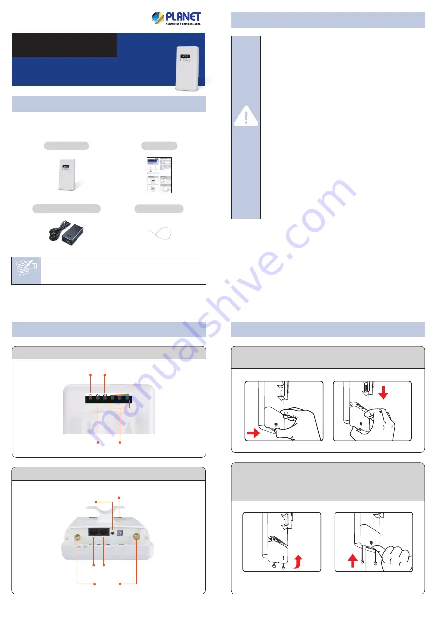
3. Physical Introduction
– 7 –
– 8 –
– 5 –
– 6 –
The above steps introduce the simple installations
and configurations of the WNAP-7335. For further
configurations of different operation modes, please
refer to the user manual which can be downloaded
from the website.
http://www.planet.com.tw/en/support/download.p
hp?type1=4&model=48688&type=3
If you have further questions, please contact the local dealer or
distributor where you purchased this product.
2011-E10610-000
Thank you for choosing PLANET WNAP-7335. Before installing the
AP, please verify the contents inside the package box.
If there is any item missing or damaged, please
contact the seller immediately.
STEP 2:
Plug the power cord into the DC port and the other
side into the AC socket. Then, plug the RJ45 cable
(as shown in picture 4 under Step 1) into the POE
port of the PoE injector.
STEP 1:
(A) Push the latch on the bottom of the WNAP-7335
to remove the sliding cover.
Bottom Panel Description – Port
Connect the WNAP-7335 with your PC via the PoE injector where
one end of an Ethernet cable is plugged into the LAN port of the
PoE injector while the other end into the LAN port of the PC. Power
on the WNAP-7335 from the PoE injector.
1. Click the
“Start”
button located in the lower-left corner of
your computer.
2. Click
“Control Panel”
.
3. Double-click the
“Network and Sharing Center”
icon.
4. Click
“Change Adapter Settings”
.
5. Double-click
“Local Area Connection”
.
6. Select
“Internet Protocol Version 4 (TCP/IPv4)”
and
click
“Properties”
.
7. Select
“Use the following IP address”
, and then click
the
“OK”
button twice to save the configuration. For
example, as the default IP address of the WNAP-7335 is
192.168.1.253 and the router is 192.168.1.254, then you
may choose from 192.168.1.1 to 192.168.1.252.
Default IP Address:
192.168.1.253
Default Username:
admin
Default Password:
admin
Default SSID:
WNAP-7335
STEP 1:
The Web management allows you to access and
manage the wireless AP easily. Launch the Web
browser and enter the default IP address
http://192.168.1.253
.
WNAP-7335
Quick Installation Guide
300Mbps 802.11a/n Wireless Outdoor CPE
For security reasons, it is recommended to change the
password at the first login and memorize it.
STEP 2:
When the login window pops up, please enter the
User Name and Password. The default User Name
and Password are both
“admin”
. Then click the
OK
button to continue.
STEP 3:
After you enter into the Web User Interface, go to
Wireless Basic Settings
to configure your wireless
network.
Rear Panel Description – LED Indication
Plastic Strap x 1
WNAP-7335
Quick Guide
PoE Injector & Power Cord
4. Hardware Installation
STEP 1:
Place the strap through
the slot on the back of
the WNAP-7335 and
then around the pole.
Tighten the strap to
secure the WNAP-7335.
5. Pole Mounting
Further Information:
6. Web Login
(B) Plug the RJ45 Ethernet cable into the PoE LAN Port and
connect the external antenna to the RP-SMA connectors of
the WNAP-7335. Then, slide back the cover of the
WNAP-7335 to finish the installation.
IMPORTANT SAFETY PRECAUTIONS:
1)
LIVES MAY BE AT RISK!
Please be aware of the
electrical wires around, and tighten the pole.
Carefully read the section
"OUTDOOR
INSTALLATION WARNING"
in the manual
before installation.
2) Users MUST use the
“PoE Injector”
and
“Power Cord”
shipped in the box with the
WNAP-7335. Otherwise, the product might be
damaged.
3) Users
MUST
use a proper and well-installed
surge arrestor and grounding wired with the
WNAP-7335; otherwise, a sudden lightning could
cause fatal damage to the WNAP-7335.
EMD
(Lightning) DAMAGE IS NOT COVERED
UNDER WARRANTY.
4) Users MUST have the antenna connected
first before powering on the WNAP-7335;
otherwise, damage to the WNAP-7335
might happen.
5) The Antenna is required, and must be purchased
separately.
Caution
Grounding Terminal
Reset Button
LAN2
PoE LAN
RP-SMA
RP-SMA(Male) to N-male Cable
Ethernet Cable
Ethernet Cable
PC
24V PoE Injector
Data
+
Power
Power
Data
PoE Port
LAN
POE
PoE Out
Data In
1
2
Signal Indicator
LAN 2 LED
Power LED
LAN 1 LED