

- 1 -
- 2 -
- 3 -
- 4 -
- 5 -
- 6 -
- 7 -
- 8 -
1. Package Contents
Thank you for purchasing PLANET 8-Port VDSL2 + 2-Port
Gigabit TP/SFP Managed Switch, VC-820M.
“Managed
Switch”
mentioned in this Guide refers to the VC-820M.
Open the box of the Managed Switch and carefully unpack
it. The box should contain the following items:
The Managed Switch x 1
Quick Installation Guide x 1
RS232 to RJ45 Cable x 1
Rubber Feet x 4
Two Rack-mounting Brackets with Attachment Screws x 1
Power Cord x 1
SFP Dust Cap x 2
If any item is found missing or damaged, please contact
your local reseller for replacement.
3. Terminal Setup
To configure the system, connect a serial cable to a
COM
port
on a PC or notebook computer and to the RJ45 type
of the console port of the Managed Switch.
Managed Switch
PC / Workstation
with
Terminal Emulation Software
Serial Port
RS232 to RJ45 Cable
Console Port
RJ45
Figure 3-1:
Managed Switch Console Connectivity
A terminal program is required to make the software
connection to the Managed Switch.
1. Run terminal program on the OS.
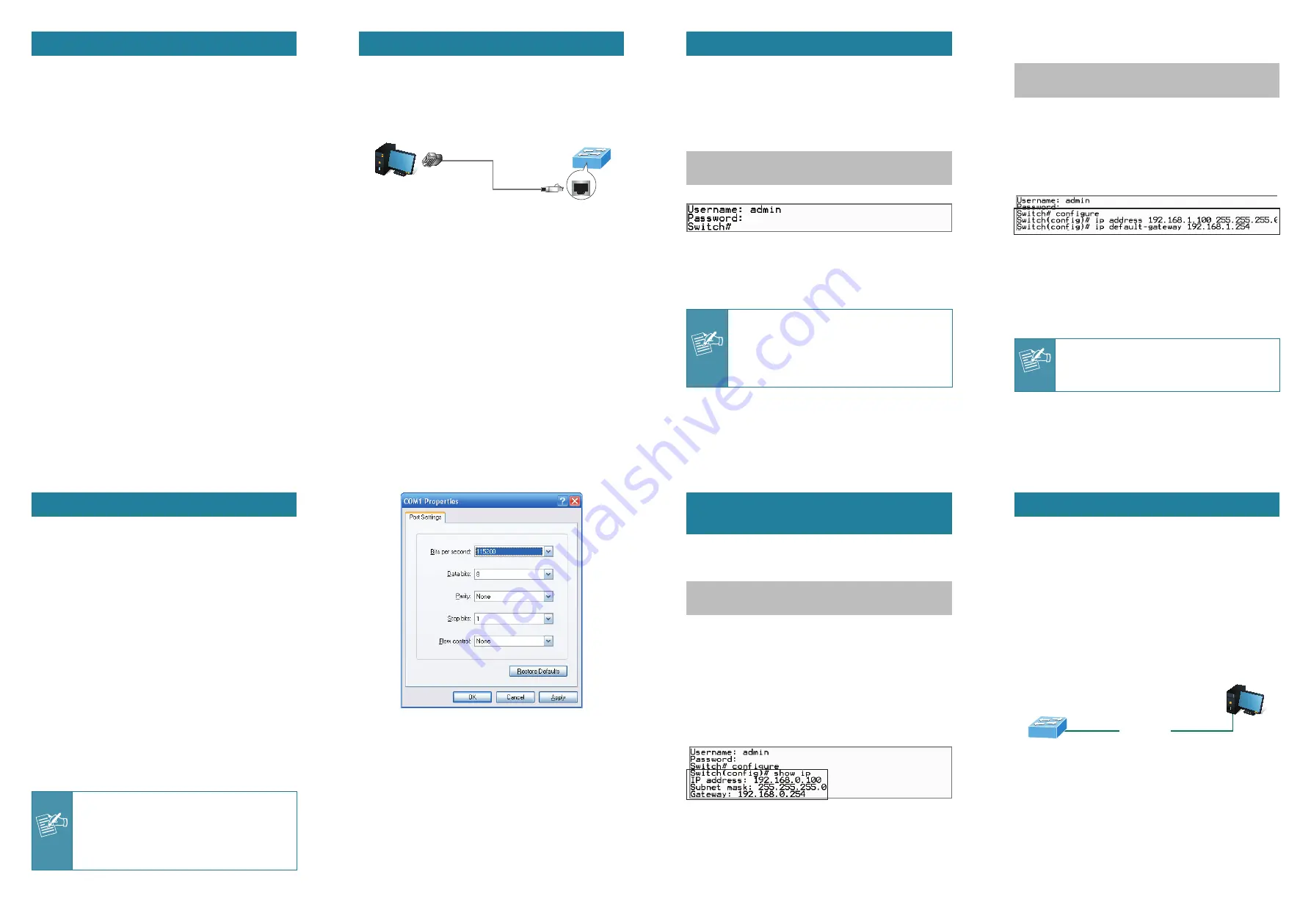
2. When the following screen appears, make sure that the
COM port should be configured as:
Baud: 115200
Data bits: 8
Parity: None
Stop bits: 1
Flow control: None
5. At the
“Switch (config)#”
prompt, enter the following
command and press
<Enter>
as shown in Figure 5-2.
Switch (config)
# ip address 192.168.1.100 255.255.255.0
Switch (config)
# ip default-gateway 192.168.1.254
The previous command would apply the following settings
for the Switch.
IP Address: 192.168.1.100
Subnet Mask: 255.255.255.0
Gateway: 192.168.1.254
Figure 5-2:
IP Address Screen
6. Repeat Step 1 to check if the IP address is changed.
If the IP is successfully configured, the Managed Switch
will apply the new IP address setting immediately. You can
access the Web interface of the Managed Switch through
the new IP address.
Note
If you are not familiar with console command
or the related parameter, enter
“?”
anytime in
console to get the help description.
4. Logon to the Console
Once the terminal is connected to the device, power on
the Managed Switch and the terminal will display “running
testing procedures”. Then, the following message asks to
log-in user name and password. The factory default user
name and password are shown as follows, and the login
screen in Figure 4-1 appears.
Username:
admin
Password:
admin
Figure 4-1:
Managed Switch Console Login Screen
The user can now enter commands to manage the
Managed Switch. For a detailed description of the
commands, please refer to the following chapters.
Note
1. For security reason, please change and
memorize the new password after this first
setup.
2. Only accept command in lowercase letter
under console interface.
2. Requirements
Workstations running Windows XP/2003/Vista/7/8/2008,
MAC OS X or later, Linux, UNIX, or other platforms are
compatible with TCP/IP protocols.
Workstations are installed with Ethernet NIC (Network
Interface Card)
Serial Port Connection (Terminal)
The above Workstations come with COM Port (DB9) or
USB-to-RS232 converter.
The above Workstations have been installed with
terminal emulator, such as Hyper Terminal included in
Windows XP/2003.
Serial cable -- one end is attached to the RS232 serial
port, while the other end to the console port of the
Managed Switch.
Ethernet Port Connection
Network cables -- Use standard network (UTP) cables
with RJ45 connectors.
The above PC is installed with Web browser and JAVA
runtime environment plug-in.
Note
It is recommended to use Internet Explore
8.0 or above to access the Managed Switch.
If the Web interface of the Managed Switch is
not accessible, please turn off the anti-virus
software or firewall and then try it again.
Figure 3-2:
COM Port Configuration
5. Configuring IP Address via the
Console
The Managed Switch is shipped with default IP address as
follows:
IP Address:
192.168.0.100
Subnet Mask:
255.255.255.0
To check the current IP address or modify a new IP address
for the Switch, please use the procedures as follows:
Show the current IP address
1. At the
“Switch#”
prompt, enter
“configure”
.
2. At the
“Switch(config)#”
prompt, enter
“show ip”
.
3. The screen displays the current IP address, subnet mask
and gateway as shown in Figure 5-1.
Figure 5-1:
IP Information Screen
Configuring IP address
4. At the
“Switch#”
prompt, enter
“configure”
.
6. Starting Web Management
The following shows how to start up the
Web
Management
of the Managed Switch. Note the Managed
Switch is configured through an Ethernet connection. Please
make sure the manager PC must be set on the same
IP
subnet address
.
For example, the default IP address of the Managed Switch
is
192.168.0.100
, then the manager PC should be set at
192.168.0.x
(where x is a number between 1 and 254,
except 100), and the default subnet mask is 255.255.255.0.
PC / Workstation
with Web Browser
192.168.0.x
Managed Switch
RJ45/UTP Cable
IP Address:
192.168.0.100
Figure 6-1:
IP Management Diagram


