


UPS Functional Descriptions
UPS-Manual
10
EN
4.
Outlet Turn Off When Battery Lower than
- select this option to automatically disable
the outlet at the specified remaining battery
power capacity(%) during battery mode to
shed the less critical loads to prolong battery
back-up time for the other more critical loads
connected to the UPS.
5.
Outlet Turn Off When Overload
– select
this option to automatically disable the outlet
during overload condition (bypass mode) to
possibly allow the more critical loads:
•
To be continually supplied via Bypass
without shut down
6. Click on “setting” to confirm the configura-
tions. The UPS will beep twice acknowledge
setting is successful.
7.
Manual Control Switch
– Click “On” or “Off”
to manually enabled or disabled the pro-
grammable outlets, overriding all previous
settings.
3.4. Communication Port Explanation
The UPS is equip with EPO dry contacts input,
true RS232 & USB Communication port as
standard to provide communication with bun-
dled UPS monitoring software for remote
monitoring of UPS status via PC.
The bundled software of the UPS is compatible
with many operating systems such as Windows
98, & 2000, ME, NT, XP and Vista. For other
applications such as Novell, NetWare, Unix, Li-
nux, please contact your local dealer for suit-
able software.
All the communication ports (including optional
cards) can be active & use simultaneously to
monitor the UPS status. However only 1 com-
munication interface at any one time with the
highest priority has the ability to command &
control the UPS. The priority of these commu-
nication interfaces are as follow:
Highest Priority (in descending order),
1) EPO input port
2) Optional Interface card
3) USB
4) RS232
3.4.1.
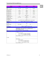
True RS232 Port Descriptions
The RS232 interface shall be set as follows:
Baud Rate
2400 bps
Data Length
8 bits
Stop Bit
1 bit
Parity
None
The Pin Assignments of the true RS232 port
are illustrated as follows:
3.4.2.
USB Port Descriptions
The USB communication protocol definition as
below:
1. Comply with USB version 1.0, 1.5Mbps
2. Comply with USB HID Version 1.0.
3. The Pin Assignments of the USB port:
3.4.3.
EPO (Emergency Power Off)
The Pin assignments of the EPO Input port are:
1
EPO+
2
Ground
To enable the EPO function, please short Pin 1
& 2.
1
2
3
4
5
6
7
8
9
Pin 3: RS232 Rx
Pin 2: RS232 Tx
Pin 5: Ground
1
VCC (+5V)
2
D
-
3
D +
4
Ground
1
2
Содержание PMC 12
Страница 28: ...Technical Informations UPS Manual 28 EN ...