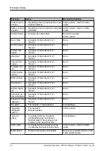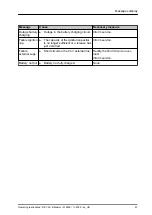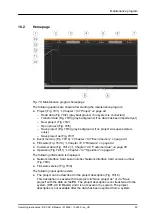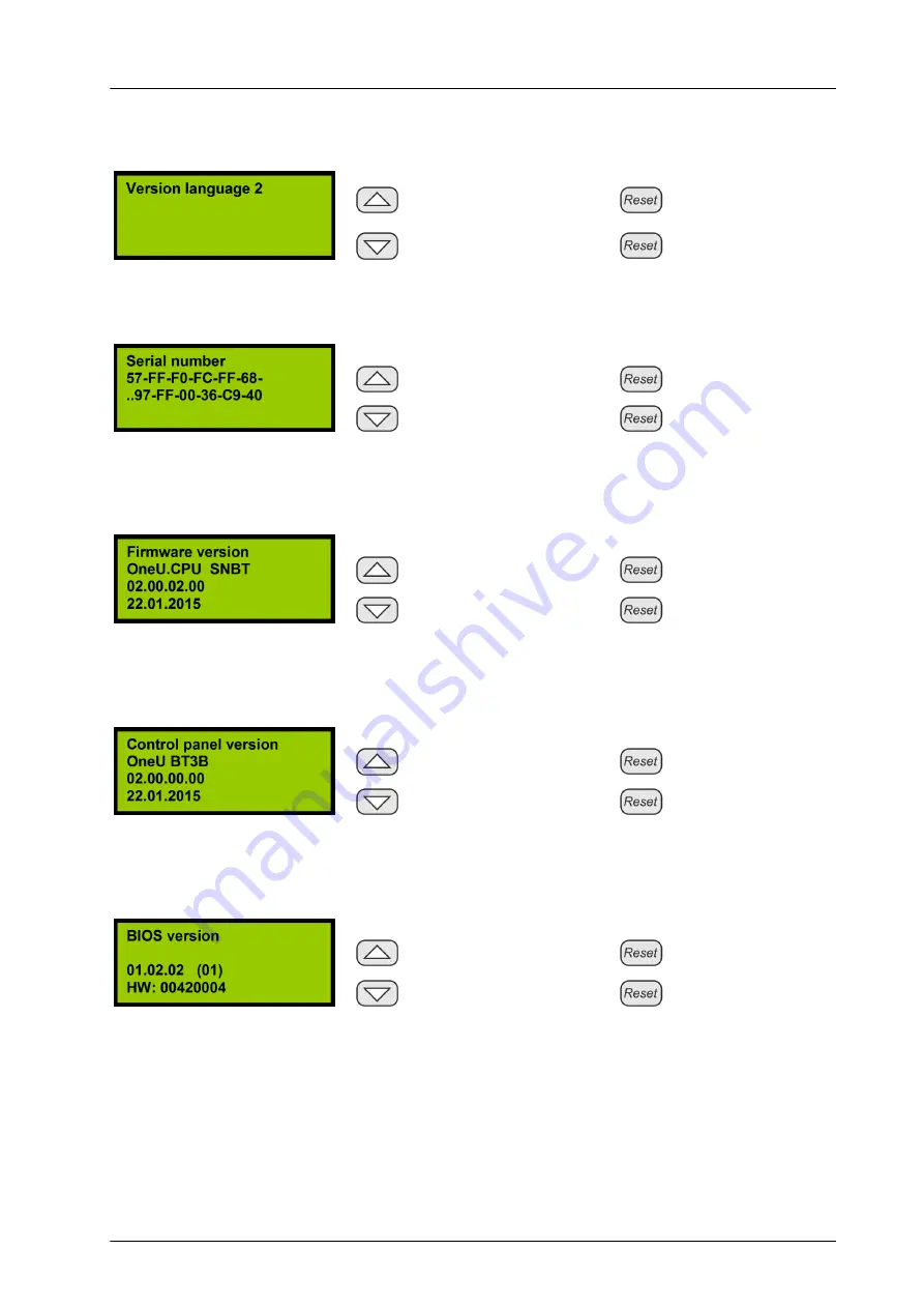
background image


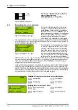
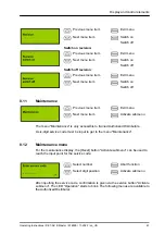
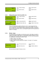
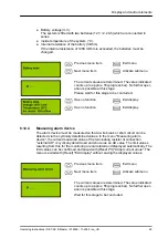
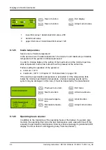
Previous submenu

item


Return to main

menu

Next submenu item


Select function

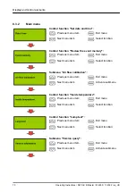
Description of the menu functions

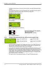
Query the serial number:

Return to menu


Return to menu

Return to menu


Return to menu

The following information is displayed: The globally unique serial number of the card

for the Network Interface.

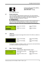
Query Firmware version:

Return to menu


Return to menu

Return to menu


Return to menu

The following information is displayed: System name, version number and the date

of version creation.

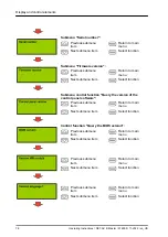
Query the version of the control panel software:

Return to menu


Return to menu

Return to menu


Return to menu

The following information is displayed: System name, version number and the date

of version creation.

Query the BIOS version:

Return to menu


Return to menu

Return to menu


Return to menu

The following information is displayed: Version number and hardware identification.

Display and control elements

Operating Instructions / DET-AC III Master / 916005 / 11-2022 / en_US


79

Содержание DET-AC III Master

Страница 1: ...Mounting installation and operating instructions DET AC III Master Active Extinguishing System DK 7338 121 ...

Страница 2: ...ument before starting any work This document is a mandatory part of the system and should therefore always be stored freely accessible and for further usage Document identification Document name Language en_US Document no 100046739 DOC ID 100153985 Approval modification no ES22 095 Part no 916005 Revision 07 Version 01 Edition 11 2022 Operating Instructions DET AC III Master 916005 11 2022 en_US 2...

Страница 3: ...ation of personnel 18 3 7 Instruction 20 3 8 Personal protective equipment 20 3 9 Operator s responsibility 21 3 9 1 Owner 21 3 9 2 Owner s obligations 21 3 10 Responsibility of the Authorized Distributor 22 3 10 1 Authorized Distributor 22 3 10 2 Obligations of the Authorized Distributor 22 3 11 Signage 23 3 12 Environmental protection 23 3 13 Behavior in the event of a fire 24 3 13 1 Preventive ...

Страница 4: ... instructions 37 6 2 2 Installation steps and functional test 38 6 2 3 Temperature indicator 42 6 2 4 Language setting for display and operation 42 6 2 5 Suction pipe installation instructions 43 6 2 6 Instructions for the use of the DET AC III Master system with simultaneous use of an automatic door opening ADO 47 6 2 7 Setting air flow calibration 48 6 2 8 Checking the failure and alarm function...

Страница 5: ...ng filter time 76 8 7 Inside temperature 77 8 8 Lamp test 77 8 9 Menu Version information 77 8 10 Revision 80 8 11 Maintenance 81 8 12 Maintenance menu 81 8 12 1 Extinguishing agent monitoring filter time 83 8 12 2 Battery change 83 8 12 3 Battery state 84 8 12 4 Measuring alarm device 85 8 12 5 Inside temperature 86 8 12 6 Operating hours counter 86 9 Messages display 88 10 Maintenance program 92...

Страница 6: ...rature indicator 105 11 2 11 Checking the setting of date and time 105 11 2 12 Checking the set integration time for air flow monitoring 105 11 2 13 Checking the last battery change 105 11 2 14 Checking the function of the door contact switch 106 11 2 15 Checking the blocking switch 106 11 2 16 Checking for proper connection of the transmission 106 11 2 17 Checking whether shutdown occurs 106 11 2...

Страница 7: ...lease 110 11 3 1 Safety instructions for the tank change 111 11 3 2 Removal 112 11 3 3 Disposal of the old tank and installation of a new tank 114 11 4 Firmware update 115 12 Spare parts accessories consumables and tools 116 13 Final shutdown disassembly and disposal 118 13 1 Final shutdown and disassembly 118 13 2 Disposal 118 14 Technical data 120 15 Index 123 Table of contents Operating Instruc...

Страница 8: ...τε το προϊόν εάν δεν έχετε κατανοήσει πλήρως τις παρακάτω οδηγίες Gaeilge Ná déan an táirge a shuiteáil a thosú agus a chothabháil mura dtuigeann tú na treoracha seo go soiléir Ná oibrigh an táirge mura dtuigeann tú go soi léir na treoracha thíos Italiano Montare il prodotto metterlo in funzione ed eseguirne la manutenzione solo se si sono comprese appieno le seguenti istruzioni Utilizzare il prod...

Страница 9: ...ujte výrobok iba vtedy pokiaľ ste jasne pochopili tento návod Slovenščina Izdelek vgradite zaženite in vzdržujte samo če ste dobro razumeli navodila v nadaljevanju Izdelek upravljajte samo če ste dobro razu meli navodila v nadaljevanju Čeština Namontujte spusťte do provozu a udržujte produkt pouze tehdy když jste jasně pochopili tento návod Obsluhujte produkt pouze tehdy když jste jasně pochopili ...

Страница 10: ...l card CPU3 8 Suction pipe connection 9 Fan 10 Power supply 11 Emergency power supply batteries 12 Discharge nozzle 13 Front panel with display and control panel 14 Control panel card BT3 2 2 Abstract The active extinguishing system DET AC III Master which is intended for installation in closed 19 cabinets e g server network or switch cabinets is a stand alone compact unit that was developed to de...

Страница 11: ...int 2 2 675235 47R end of line resistor with 1N4007 rectifier diode for alarm device 2 1 917751 470 Ω 0 5 W resistor for door contact manual call point 3 1 675223 1K end of line resistor for RJ12 plug door contact switch 3 1 908119 22K end of line resistor for RJ12 plug door contact switch 3 1 906913 Rail left 3 1 915914 Rail right 3 1 915915 M4 6 oval head screw for mounting the left and right ra...

Страница 12: ...One of the following Rittal products must be used to establish network capability CMC Processing Unit IoT interface Power Distribution Unit PDU metered metered plus switched managed 2 4 Limitations of liability All specifications and information provided in this operating instruction have been compiled in consideration of all applicable standards and regulations as well as the state of the art The...

Страница 13: ... and compliance with all standards codes and ordinances The construction and use of the system described in this operating instruction are only to be used for the purposes that are shown and described The manufacturer or private labeler provides no warranty or guarantee for uses not described in this specification or for uses that do not comply with legal and local regulations Graphs or reports us...

Страница 14: ...th a low risk level If the danger is not avoided it may result in minor or moderate injury NOTICE This signal word describes a danger with a low risk level If the danger is not avoided it may result in property and environmental damage Further markings INFORMATION This marking emphasizes useful tips and recommendations as well as information for efficient and trouble free operation In instructions...

Страница 15: ...hich are described in this oper ating instruction Ä Chapter 6 Assembly and installation on page 35 Ä Chapter 11 Maintenance on page 99 Incorrect use Any other use exceeding or deviating from the scope of intended use is considered incorrect use L WARNING Danger due to misuse Misuse of the system can lead to personal injury and property damage No structural changes to the device to be protected or ...

Страница 16: ... deviate from each other due to world wide use the applicable national regulations and laws at the site of operation are to be observed in so far as they contradict the information provided in this operating instruction As a general rule the following information in particular is to be observed adhered to National safety and accident prevention regulations National standards and laws in particular...

Страница 17: ...sk of injury from developing products of decomposition and fire smoke Fires generate decomposition products which may lead to chronic health impair ments if inhaled and if there is contact with the skin Do not use the system if in normal operation surface temperatures in excess of 500 C 932 F are to be expected Keep the extinguishing zone closed in the event of a fire e g do not open any of the sw...

Страница 18: ...lified persons pose a hazard Inadequately qualified persons cannot assess the risks involved in handling the system They expose themselves and others to the risk of severe or fatal injuries All work should be carried out only by persons qualified to do so Before starting any work the following persons must be identified who have the knowledge required to operate the system A person to be responsib...

Страница 19: ...arity with all applicable standards and regulations A qualified electrician must also provide proof of his her professional qualification that confirms his her capacity to perform work on electrical systems The qualified electrician must comply with the provisions of all applicable legal regu lations regarding accident prevention Qualified specialist personnel Qualified specialist personnel are pe...

Страница 20: ...n the individual sections of this document when carrying out the various tasks Additional personal protective equipment may also be required due to local condi tions directives company specifications etc The following describes the required personal protective equipment which is referred to again at the beginning of the respective sections of this document Protective goggles Protective goggles cov...

Страница 21: ...ed throughout this operating instruction The owner must document the results of the inspections in the log book The owner must report any detected defects and or damage to the Author ized Distributor which he she is not authorized to rectify independently The owner must document all shutdowns and failures the system experi ences in the log book of the system The Occupational Safety and Health Act ...

Страница 22: ...nt correct nominal fill density given In this regard the following particularly applies The Authorized Distributor must comply with the applicable local regulations and consider these regulations in the selection of the system The Authorized Distributor must take the current state of the technology into consideration at all times The Occupational Safety and Health Act of 1970 specifies that a safe...

Страница 23: ... the system and its associated dangers Fig 2 Marking of the extinguishing zone example 1 Included in the scope of delivery 3 12 Environmental protection NOTICE Danger to the environment due to incorrect handling of materials that can harm the environment In case of incorrect handling of materials that can harm the environment especially improper disposal there can be significant damage to the envi...

Страница 24: ...d rescue equipment as well as options for releasing the system manually Keep access paths clear for rescue vehicles 3 13 2 Steps in the event of a fire L WARNING Risk of death due to fire Severe fire smoke may develop when a fire erupts and while the fire is being extin guished Fire smoke development may result in severe airway damage or death Keep the extinguishing zone closed in the event of a f...

Страница 25: ...ing delivery as well as during the transport to its final destination and comply with the sym bols and information displayed on the packaging Only remove packaging immediately prior to installation 4 1 Transport inspection 1 Check all system parts for completeness and transport damage immediately upon receipt 2 If there is apparent external transport damage proceed as follows Note the scope of the...

Страница 26: ...ank system spare part Safety data sheet1 for Novec 1230 manufactured by 3M 1 The safety data sheets are included with the system Observe the country specific provisions for export INFORMATION Anyone who ships hazardous airfreight must be trained in accordance with IATA DGR 1 5 L CAUTION Danger due to faulty release The faulty release of the system may result in injury or property damage Before the...

Страница 27: ...enance or repair in the special original packaging it came in or in packaging equivalent to this Outer dimensions width x depth x height 675 x 875 x 210 mm Weight approx 6 6 kg Tab 1 Data of the original packaging Transport and packaging Operating Instructions DET AC III Master 916005 11 2022 en_US 27 ...

Страница 28: ... extracts air via pipe system from the switch cabinet to be protected The extracted air is channeled through guide plates to the fire detec tors Fig 5 5 A fire is detected as soon as the extracted air contains smoke aero sols The fire detectors are permanently monitored for operability by the electronic evalu ation and control unit on the control card Fig 5 7 If the first fire alarm threshold is r...

Страница 29: ... configured for a 4 hour uninterrupted operation of the system The operation and display of the current state of the system is by means of the control panel that is installed To display the current state this has on the one hand 6 LED indicators and on the other hand an LCD display The LEDs serve to display the main alarms and failures Ä Chapter 8 1 LED displays on page 67 while the individual sta...

Страница 30: ...C III Master DET AC III Slave RJ12 DEC Ä Chapter 5 3 9 Connection for networking on page 34 10 External alarm device Ä Chapter 5 3 4 Connection of external alarm device on page 33 delivery with terminating resistor 47 Ω and diode 1N4007 11 Connection for external fill level monitoring and triggering of external tank Ä Chapter 5 3 5 Connection of external fill level monitoring and triggering of ext...

Страница 31: ...le with plastic sleeve 0 25 mm2 2 5 mm2 Conductor cross section flexible AWG kcmil 24 12 Two conductors of equal cross sections rigid 0 2 mm2 1 mm2 Two conductors of equal cross sections flexible 0 2 mm2 1 5 mm2 Two conductors of equal cross sections flexible with wire end ferrule without plastic sleeve 0 25 mm2 1 mm2 Two conductors of equal cross sections flexible with twin wire end ferrule with ...

Страница 32: ... Interfaces to the Monitoring System 6 7 8 16 Fig 11 CMC connections The active extinguishing system DET AC III Master has a CAN bus interface Fig 11 16 for connecting to various network capable monitoring systems from Rittal All states and messages that are listed in the table shown below can be queried through it Binary alarm states Binary failure states Messages External release Failure manual ...

Страница 33: ...l tank Connection of an external extinguishing container is only possible with variant EFD III The external tank must be enabled in the program for this When activated the output Fig 13 11 switches the system voltage 21 V to 27 V to the connection technology at an output current of 500 mA with a maximum duration of 2 seconds 5 3 6 Manual call point connection An externally accessible manual releas...

Страница 34: ...d settings can be made via the USB port Fig 16 15 This for example includes reading out the error memory set ting the time and date uploading new Firm ware Further information Ä Chapter 10 Maintenance program on page 92 INFORMATION The USB port is not suitable as a power source 5 3 9 Connection for networking The system DET AC III Slave is connected via the connections RJ12 DEC Fig 17 9 A total of...

Страница 35: ...which metallic or plastic decomposition gases or vapors can be extracted by the aspirating smoke detection system Mounting the system in areas with shocks and vibrations is possible subject to certain conditions The system has been tested according to standards DIN EN 54 20 and DIN EN 54 4 Vibration Operation only in closed cabinets If cooling units are installed make sure that no air exchange wit...

Страница 36: ...sible C Installation of the system in the closed 19 cabinet without cooling air circuit and without visible openings is possible Installation of the system in differently equipped 19 cabinets is possible only fol lowing consultation with the Authorized Distributor 6 2 Installation and commissioning Personnel n Authorized Distributor Protective equipment n Safety goggles n Safety gloves n Safety fo...

Страница 37: ...al free contacts INFORMATION Make sure at an early stage that the cabinet to be protected meets all of the requirements in regard to space needs tightness and mounting options so that the system can be installed in a proper functional manner INFORMATION Be sure to keep the packaging the system came in The system can only be sent for maintenance or repair in the special original packaging it came i...

Страница 38: ...prior to installation commissioning The system is to be placed in the upper third of the 19 cabinet to be protected In this case it is to be observed that the suction pipe with suction bores is installed as described in Ä Chapter 6 2 5 Suction pipe installation instructions on page 43 the positioning of the suction pipes is dependent on the direction of the air flow If the suction pipes are instal...

Страница 39: ...ront enclosure cover 7 Activate the system using the battery button Fig 21 Battery ON 8 Check whether the Failure LED Fig 22 1 lights up and the display shows Failure tank triggering 9 When using door contact switches configure the settings Ä Chapter 6 3 5 Door contact blocking on page 55 10 When using additional extinguishing units DET AC III Slave configure the settings Ä Chapter 6 3 6 Combinati...

Страница 40: ...start up the system press the Battery ON button Fig 21 21 Connect the mains power supply If a mains power supply is unavailable shut down the system again using the Battery OFF Fig 21 following installation to prevent the batteries from discharging 22 Connect the door contact switches Ä Chapter 6 3 5 Door contact blocking on page 55 23 Set the air flow monitoring Ä Chapter 8 6 Air flow calibration...

Страница 41: ...king switch Fig 20 arrow to Agent con nect not blocked Fig 20 Ⅰ ð The system is ready for operation and activation 35 Attach the Gas based extinguishing system Danger to health sign Fig 26 in a clearly legible position on the cabinet You should preferably attach the warning signs to the outside of the cabinet doors Alternatively you can also attach the warning signs on a side wall if they will dra...

Страница 42: ...ark in color and have the system replaced 6 2 4 Language setting for display and operation The system can communicate in German and English German is pre set by the manufacturer but can be changed to Eng lish via a DIP switch Fig 29 Proceed as follows to make the changeover 1 To block the system Switch the blocking switch Fig 30 arrow to Agent dis connect blocked Fig 30 Ⅱ 2 Disconnect the system f...

Страница 43: ... fit cables in the protected cabinet always ensure that the suction bores remain unobstructed INFORMATION The suction pipe system is a self sealing and self locking pipework system The pipe connection is fully established by connecting the pipe and fitting 1 Mount the vertical suction pipe Fig 31 in the cabinet at a point that is suitable for the fluidic system using the clamps The suction bores m...

Страница 44: ...nstalled suction pipe Perform a reaction test with a test aerosol 6 L CAUTION Faulty release due to the removal of the blocking Remove the system block only if no red LEDs are lit up and there is no fire alarm on the display 6 2 5 1 Establishing the suction bores L CAUTION Risk of injury due to incorrect detection Incorrectly produced suction bores may result in incorrect detection This can cause ...

Страница 45: ...as for red bore marks Fig 34 3 on suction pipes Cleaning agents that attack plastics must not be used under any circum stances 4 Glue the red bore marks3 into place making sure they are in the middle of the suction bores 5 If there are too many suction bores Degrease the area around the bore to be sealed Cleaning agents that attack plastics must not be used under any circum stances Glue the black ...

Страница 46: ...n the pipe up to the marking Fig 35 X and until it can be heard and felt to be in the stop 6 2 5 3 Disassembling the suction pipe Fig 36 Dismantling 1 Fig 36 1 Press down the retaining element Fig 36 a The retaining element is only recognizable as a ring from the outside 2 Fig 36 2 Pull out the pipe when the retaining element is pushed down Fig 36 a Assembly and installation Operating Instructions...

Страница 47: ... with an automatic door opening ADO In the case of an automatic door opening ADO there are flaps in the door of the 19 cabinet The flaps are opened automatically e g if the cooling system in the 19 cabinet fails L CAUTION Unwanted release due to absent blocking If the active extinguishing system DET AC III Master is used in 19 cabinets with an automatic door opening ADO from Rittal and no flap is ...

Страница 48: ...1 INFORMATION The air flow must be recalibrated when changing the equipment of the switch cab inet 6 2 8 Checking the failure and alarm function The system is ready for operation when the door is closed The green LED lights up and State OK is shown in the display If this is not the case actuate the upper Reset button Fig 39 1 The green LED then blinks twice and messages that are still pending are ...

Страница 49: ... must be performed for each of the door contact switches that are installed NOTICE Faulty release due to removal of the blocking Premature removal of the blocking can result in a faulty release and thereby cause property damage Do not stop blocking the system until there are no red LEDs lit up and there is no fire alarm shown in the display 6 2 8 3 Manual call point L CAUTION Danger of injury from...

Страница 50: ...detectors L CAUTION Danger of injury from faulty release Checking the fire detector when the system is not blocked can result in a faulty release A faulty release may cause injuries and significant property damage Block the system prior to checking the fire detector To this end switch the blocking switch on the back of the system to the Ⅱ Agent disconnect blocked position Switch the blocking switc...

Страница 51: ...nnect blocked NOTICE Faulty release due to removal of the blocking Premature removal of the blocking can result in a faulty release and thereby cause property damage Do not stop blocking the system until there are no red LEDs lit up and there is no fire alarm shown in the display 6 3 Installation and commissioning of additional electrical devices Personnel n Qualified electrician n Authorized Dist...

Страница 52: ...ilure 2 LED Extinguishing system triggered 6 3 1 Potential free contacts NOTICE Malfunction due to interrupted relay contacts When using relay contacts for external controllers the connections to the relay con tacts can be interrupted when removing the system from the protected cabinet As a result there is a danger of unwanted switching states arising from e g safety functions which use closed cir...

Страница 53: ...basis 6 3 2 External alarm devices External alarm devices such as flashlights and or horns Ä Chapter 12 Spare parts accessories consumables and tools on page 116 can be connected to output 10 Fig 48 10 This output monitors the line that is connected as well as the alarm device that is connected for wire breaks and short circuits When activating the output via a manual call point or via the fire al...

Страница 54: ...ions The system DET AC III Master also has two CAN bus interfaces Fig 50 16 through which the system can be connected directly to various monitoring systems from Rittal CMC IoT interface PDU Ä Chapter 5 3 3 Interfaces to the Monitoring System on page 32 The CMC TC is the predecessor to the CMC III and does not have a CAN bus inter face The three states Failure Fig 50 6 Fire alarm Fig 50 7 and Pre ...

Страница 55: ... to connection 13 5 13 Fig 51 Connections door contact switch L CAUTION Unwanted release due to absent blocking If no door contact switches are used the system is not blocked when the door is opened The system can however be released in the event of detection If there are no door contact switches inform all persons who are working on the control cabinet of a possible release of the system if the d...

Страница 56: ...t switch Door contact input 5 Fig 52 5 is designed for the Rittal RJ12 plug door contact switch Fig 53 2 5 13 Fig 52 Connections for door contact switches 1 2 3 2 Fig 53 Installation diagram 1 Door contact input 5 Fig 52 5 2 RJ12 plug door contact switch access sensor X1 RJ12 bushing 6 pin for connecting to the system or for series connection with an additional door contact switch X2 RJ12 bushing ...

Страница 57: ...ransparent Fig 54 2 1 kΩ Type 7320 530 transparent Fig 54 3 1 kΩ Type 7320 530 gray Fig 54 4 22 kΩ 3 Remove the pre fitted end of line resistor Fig 52 13 when using the RJ12 plug door contact switch 1 2 1 2 Fig 55 Reset button and DIP switch S3 A Setting for the transparent door contact switch B Setting for the gray door contact switch 4 On the CPU3 control card on DIP switch S3 Fig 55 2 set slide...

Страница 58: ...rule be connected to active extinguishing systems DET AC III Master of the new series Part No 7338 121 In the same way systems DET AC III Slave of the new series Part No 7338 321 can as a general rule be connected to active extinguishing systems DET AC Plus Master of the old series Part No 7338 120 The systems are fully functional However not all messages are transmitted and certain functions cann...

Страница 59: ...ter DET AC III Master Master Master Master Master Master Should a failure occur in the systems that are connected the system is denoted by Z2 Z3 Z4 or Z5 in the display in the Master 6 3 6 3 Configuring systems 1 To block the system Switch the blocking switch Fig 56 arrow to Agent dis connect blocked Fig 56 Ⅱ 2 Remove the transparent protective film in the rear section of the cover 3 L WARNING Dan...

Страница 60: ...et S7 to the identification that the system has within the networking Ä Table 2 Addressing S6 and S7 on page 61 S7 must be set to 0 for non networked systems 5 Close the transparent protective film in the rear section of the cover Fig 57 Configuration Assembly and installation Operating Instructions DET AC III Master 916005 11 2022 en_US 60 ...

Страница 61: ... Addressing S6 and S7 6 3 6 4 Connecting the energy supply and data line 1 Connect the mains supply Fig 58 2 of 100 240 V AC to the Master Fig 58 1 2 Establish the power supply Fig 58 5 between Master and first Slave Fig 58 7 See also Ä Chapter 5 3 7 Power supply on page 34 3 Establish the power supply Fig 58 6 between first Slave and next Slave Fig 58 8 4 Ensure that there is no fire message pend...

Страница 62: ...njuries and property damage Only use the blocking switch to check networking if there are no red LEDs lit up and there is no fire alarm shown in the display 6 3 6 6 Reading out the state of the respective systems The display for the current state of the system is at the Master active extinguishing system DET AC III Master or EFD III The messages of the networked devices with the identification Z2 ...

Страница 63: ...uishing can be released by actuating a manual call point Ä Chapter 12 Spare parts accessories consumables and tools on page 116 Release occurs directly after the actuation and independently of the state of the automated fire detectors Release of extinguishing by actuating a manual call point is suppressed if blocking is in place The alarm message of the manual release must be reset manually using ...

Страница 64: ...moke The states Pre alarm and Fire are generated at the system Failure messages The system monitors the most important functions Failures are shown and can be transmitted via the potential free contacts to an external display or controller INFORMATION The significance of the LEDs is explained in Ä Chapter 8 1 LED displays on page 67 The display messages are explained in Ä Chapter 9 Messages displa...

Страница 65: ...low LED Fig 63 3 also lights up if a door fitted with a door contact switch is open Failure tank triggering is shown in the display Prior to removing the blocking make sure that the upper red LED Fig 63 1 is not illuminated as the extinguishing process will otherwise be initiated immedi ately 1 LED Extinguishing system triggered 2 LED Failure 3 LED Blocked 4 Blocking switch Ⅰ Agent connect not blo...

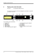
Страница 66: ... the front Fig 64 Display and control elements 1 Display LCD 2 Up Button 3 Down Button 4 LED Operation 5 LED Shutdown 6 LED Extinguishing system triggered 7 LED Extinguishing system released 8 LED Failure 9 LED Blocked 10 Reset Button 11 Reset PS Button to reset the power supply Display and control elements Operating Instructions DET AC III Master 916005 11 2022 en_US 66 ...

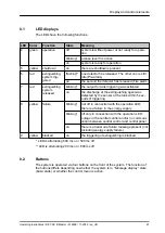
Страница 67: ...onds of triggering 8 yellow failure blinking not off in connection with the operation LED there is a failure in the energy supply blinking off only in connection with the operation LED outage in the central control and or no communi cation between central control and control panel on there is at least one failure message present not including energy supply failure 9 yellow blocked on the triggerin...

Страница 68: ...Enter The submenu is activated if Reset is actuated in the main menu on an entry that refers to a submenu If no submenu exists then activation of the designation control function occurs Tab 3 Function of the control buttons 8 3 Display The display serves to show in text form each of the current individual messages that are pending Moreover the text display enables menu guided operation of the syst...

Страница 69: ... more recent messages present which can be retrieved using the Down button If no further input occurs in this state for 30 seconds the display changes automati cally into the basic state of the message display display of the most recent mes sage Control menus If the control panel is in Message display state activation of the control menu occurs through simultaneous actuation of the arrow buttons U...

Страница 70: ...alibration Previous menu item Exit menu Next menu item Activate submenu Control function Inside temperature Previous menu item Exit menu Next menu item Select function Control function Lamp test Previous menu item Exit menu Next menu item Select function Submenu Version query Previous menu item Exit menu Next menu item Activate submenu Display and control elements Operating Instructions DET AC III...

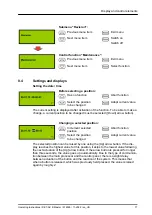
Страница 71: ... Abort function Select the position to be changed Adopt current value The selected position can be raised by one using the Up arrow button If the dis play reaches the highest value for this position it skips to the lowest value following the next actuation of the Up arrow button If the arrow button is pressed for longer than three seconds the value goes up automatically Due to the type of communic...

Страница 72: ... In the next display of the event memory the event which previously has the number 2 now has the number 1 the saved events move downward so that the new event can be added at the top The numbering in the event memory does not in any way relate to the number that was shown for the event in the message display when the event was still current In the event memory display it is possible to move from a...

Страница 73: ... recent messages present Display of the oldest saved event Has no function Exit display To next message To most recent mes sage 8 6 Air flow calibration Submenu Air flow calibration Control function Display of the current air flow measured value Previous submenu item Return to main menu Next submenu item Select function Control function Automatic calibration of the air flow monitoring Previous sub...

Страница 74: ...ured value currently present as well as the monitoring thresholds currently set are displayed The measured value is updated cyclically so that changes to it are displayed 8 6 1 Automatic calibration of the air flow monitoring Determining the current values The current values are determined The value displayed counts up to 64 progress bar No further operation is possible at this stage Wait for this...

Страница 75: ...rance can be raised by 20 or 40 as a further measure For the determined values become effective they must be adopted Reset PS button Fig 72 1 8 6 2 Manual calibration of the air flow monitoring INFORMATION Prior to manual calibration an automatic calibration including setting the thresholds 10 20 or 40 must be performed and confirmed Ä Chapter 8 6 1 Auto matic calibration of the air flow monitorin...

Страница 76: ... for a short time An integration time filter time can be set in seconds in order to avoid a failure If an arrow button is pressed for longer than three seconds the value goes up auto matically Due to the type of communication between the main processor and the control panel there is a slight delay between actuation of the button and the reaction of the system This means that when a button is relea...

Страница 77: ...sults as the system may be damaged In this case it must be inspected by the manufacturer Has no function Exit display Has no function Exit display 8 8 Lamp test All of the display s segments are triggered black and all of the LEDs are switched on continuously Exit test display Exit test display Exit test display Exit test display The lamp test is exited by actuating any button The lamp test is exi...

Страница 78: ...ol panel software Previous submenu item Return to main menu Next submenu item Select function Control function Query the BIOS version Previous submenu item Return to main menu Next submenu item Select function Previous submenu item Return to main menu Next submenu item Select function Previous submenu item Return to main menu Next submenu item Select function Display and control elements Operating...

Страница 79: ...turn to menu The following information is displayed System name version number and the date of version creation Query the version of the control panel software Return to menu Return to menu Return to menu Return to menu The following information is displayed System name version number and the date of version creation Query the BIOS version Return to menu Return to menu Return to menu Return to men...

Страница 80: ...ayed Language name language pack version 8 10 Revision Menu function Revision Via the menu function Revision the system can be switched to revision operation and or revision operation can be ended again The following triggerings are suppressed in revision operation Connecting terminal for relay output Pre alarm Fig 77 1 Connecting terminal for relay output Fire alarm Fig 77 2 Connecting terminal f...

Страница 81: ...stributors A six digit service code must be input to get to the menu Maintenance 8 12 Maintenance menu For the maintenance display the Reset button Activate submenu can be used to reach the input point for the service code Select number Abort function Select digit position Activate submenu After inputting the service code confirmation is given via the service button Activate submenu The LED Operat...

Страница 82: ...tivate submenu Previous menu item Exit menu Next menu item Activate submenu Previous menu item Exit menu Next menu item Activate submenu Previous menu item Exit menu Next menu item Activate submenu Diagnosis memory Confirm change Abort function Abort function Abort function Display and control elements Operating Instructions DET AC III Master 916005 11 2022 en_US 82 ...

Страница 83: ...tinguishing agent loss is recognized and shown on the display 8 12 2 Battery change The operating time of the battery is monitored by a timer If the battery exceeds the maximum permissible operating time a corresponding message indicator is shown in the display and the system goes into failure state There are the following options for resetting this monitoring after a battery change Battery change...

Страница 84: ...essary a previously displayed failure message prompting a battery change is cancelled If the function is aborted a warning message appears Return to menu Return to menu Return to menu Return to menu If this message is displayed the operating hours counter for the battery was not reset It proceeds from the last saved value Where applicable a previously dis played failure message prompting a battery...

Страница 85: ...a wire break or short circuit can be detected via the cyclically determined values In the menu Measuring alarm device the current measured value of the terminating resistor at connection external AD is cyclically determined and shown as an AD value The limit values resulting from this for the monitoring are calculated and displayed automatically The limit values can be confirmed and saved with Res...

Страница 86: ... page 120 If the maximum permissible temperature is exceeded or if the temperature falls below the minimum permissible temperature a failure message results as the system may be damaged In this case it must be inspected by the manufacturer Previous menu item Exit menu Next menu item Activate submenu Increase tempera ture Abort function Decrease tempera ture Adopt current value 8 12 6 Operating hou...

Страница 87: ...utton Resetting in this way has no effect on the monitoring of the operating time of the bat tery NOTICE Damage due to incorrectly recorded operating hours Both the operating hours counter for the maintenance interval and the operating hours counter for the batteries are based on the real time clock that is installed Adjusting this clock can under certain circumstances affect correct recording of ...

Страница 88: ...point Ä Chapter 6 3 7 Manual call point on page 63 Fire alarm detector 1 Fire is detected None Fire alarm detector 2 Fire is detected None Blocking by door cont Extinguishing system is blocked by the door being opened Close the door check the door contact switch Check whether there is still a terminating resistor in the RJ12 plug or connected to the door contact clamp Failure door contact Wire bre...

Страница 89: ...ist replace the air filter Failure detector 1 Detector head 1 defective Detector head 1 is missing Inform service Failure detector 2 Detector head 2 defective Detector head 2 is missing Inform service Failure Com munication Power supply 24 V to the slave is interrupted Check insert power supply 24 V Electrical defect CAN bus connecting cable Master Slave to the Slaves not connected Addressing at t...

Страница 90: ...tons Up Down None BIOS version Actuation of the buttons Up Down None Checksums Actuation of the buttons Up Down None Air flow indica tion Actuation of the buttons Up Down None Automatic air flow calibration Actuation of the buttons Up Down None Manual air flow calibration Actuation of the buttons Up Down None Pre alarm Fire detector 1 has detected Acknowledge Triggering extinguish system Fire dete...

Страница 91: ...y of the ignition capacitor is no longer sufficient or a release has just occurred Inform service Failure external supp Short circuit on the 24 V external line Rectify the short circuit or over load Inform service Battery not full Battery not fully charged None Messages display Operating Instructions DET AC III Master 916005 11 2022 en_US 91 ...

Страница 92: ...ter In most cases the maintenance program can only be installed with Administrator s rights Proceed as follows to do this 1 Copy the zip file into a directory and unpack 2 Create a shortcut on the desktop 3 Open the window to change the shortcut Properties Shortcut Target 4 Change the extension of the shortcut to Wartungsprogramm exe hamburg Adding hamburg enables additional functions for the Auth...

Страница 93: ... 94 Customer data Fig 79 12 Ä Chapter 10 6 Customer data on page 95 Operation Fig 79 11 Ä Chapter 10 7 Operation on page 97 The following information is displayed Network Interface Card serial number Network Interface Card version number Fig 79 8 Firmware version Fig 79 9 The following input option exists The project can be described in the project description Fig 79 10 This description is saved w...

Страница 94: ...pened and transferred to the system Saving a project The project is saved if the path is known Saving a project as A project is saved under a previously input path and name 10 4 Event memory Pending and past events can be displayed and saved using the event memory AMEM events currently pending EMEM all events that have occurred up to the point in question DMEM Firmware diagnostics records 10 5 Fir...

Страница 95: ...sed to describe the system project can be entered in the description During data transfer this description is transferred to the system DET AC III Master Any text which is used to describe the system project can be entered in the description During data transfer this description is transferred to the system Date Prog Date when customer data was last transferred System password Defines the six digi...

Страница 96: ...ng filter time This fault is only displayed after 120 seconds Extinguishing delay Extinguishing is delayed by 0 seconds The delay time can be set to a maximum of 120 seconds When configuring the setting observe the applicable provisions guidelines and laws at the location Factory setting 10 6 4 Threshold values Air flow monitoring lower threshold the lower value of the air flow calibration is disp...

Страница 97: ...devices on page 53 Triggering the internal tank Battery change Adopts the system s current time state as the time of the last battery change No safety queries occur in this process in contrast to when this function is activated on the control panel Maintenance Adopts the system s current time state as the time of the last maintenance Reset Resets the system Reset PS Resets battery failures USB CPU...

Страница 98: ...ible if the mainte nance program displays No device connected Time Read out time Reads the time out of the CPU of the system and displays it in the time and date fields Set date time Writes the values from the time and date field into the CPU of the system System time Sets the time and date fields to the PC system time Time date field Defines the time that is to be written into the system by means...

Страница 99: ...nd insufficient or non performed regular checks and maintenance 11 1 Regular checks by the owner Personnel n Person in charge of the system Daily checks The system must be in a failure free state operating state without failure or alarm the green LED lights up there are no yellow failure LEDs or red alarm LEDs lit up or blinking If the system is connected to a CMC III the control can also be done ...

Страница 100: ... death or severe physical injury due to electric shock All tasks at the open system may only be performed by electricians with appro priate training L CAUTION Danger of injury from faulty release A faulty release of the system may cause injuries and property damage Block all networked systems using the blocking switch Fig 80 arrow prior to performing maintenance work switch the blocking switch to ...

Страница 101: ...ce Maintenance every 2 years Maintenance every 10 years Ä Chapter 11 2 1 Checking for proper installation on page 104 X Ä Chapter 11 2 2 Checking for external damage on page 104 X Ä Chapter 11 2 3 Recording the WA No Part No F No on page 104 X Ä Chapter 11 2 4 Recording the date of the current mainte nance inspection on page 104 X Ä Chapter 11 2 5 Recording the current version on page 104 X Ä Chap...

Страница 102: ... Ä Chapter 11 2 20 Cleaning the pipe system on page 106 X Ä Chapter 11 2 21 Changing the batteries on page 107 X Ä Chapter 11 2 22 Changing the battery control card CPU3 on page 107 X Ä Chapter 11 2 23 Checking the DIP switch on the control card CPU3 on page 107 X Ä Chapter 11 2 24 Checking the networking of the systems on page 107 X Ä Chapter 11 2 25 Changing the filter on page 108 X Ä Chapter 11...

Страница 103: ... failures Ä Chapter 8 5 Reviewing the event memory on page 72 In the course of maintenance the system is checked fully and where applicable put back into target state Non compliance with these intervals can cause failures and false alarms and consequently to faulty extinguishing During maintenance the total weight of the system must be reported Maintenance every two years Authorized Distributor Th...

Страница 104: ...1 2 5 Recording the current version Refer to the control menu for the current version states Ä Chapter 8 9 Menu Ver sion information on page 77 Firmware version Control panel version BIOS version Record the different versions in the service report and compare with the old data A deviation is to be noted with an explanation 11 2 6 Checking and recalibrating the air flow measured values Refer to the...

Страница 105: ...heck the temperature indicator on the small cover in the front section for tempera tures possibly being exceeded Ä Chapter 6 2 3 Temperature indicator on page 42 Defects in electrical components can result from the temperature being exceeded Contact the Authorized Distributor if the temperature indicator is dark in color and have the system replaced 11 2 11 Checking the setting of date and time Ch...

Страница 106: ...s e g fans can be transmitted via the potential free relay outputs Check whether shutdown of the external devices is functioning 11 2 18 Reading out and transferring data Read out and archive the data of the system for every maintenance and installation Ä Chapter 10 3 Project on page 94 describes how customer data can be read out and changed 11 2 19 Checking the electrical connections L WARNING Ri...

Страница 107: ...he replacement of the battery control card CPU3 Fig 81 1 must be reported After the replacement of the battery check the real time 11 2 23 Checking the DIP switch on the control card CPU3 The DIP switch for the door contact as well as for the language setting can be found on the control card CPU3 The setting of the switch for the door contact can be found in Ä Chapter 6 3 5 Door contact blocking o...

Страница 108: ... housing e g dust lint 11 2 27 Checking loss monitoring To check the function of the loss check the system must be connected electrically and raised on the right hand side at an angle of roughly 20 In the display Fig 83 1 the message Extinguishing agent loss is shown INFORMATION Set the filter time for the check to zero reset it to the set value afterwards 11 2 28 Power supply L WARNING Risk of de...

Страница 109: ...m must be checked and reported A calibrated scale for loads of up to 20 kg and 10 g resolution is needed for this 11 2 31 Testing the release L CAUTION Risk of injury from faulty release A faulty release of the system may cause injuries and property damage Block the system before the release is tested to avoid unwanted extinguishing This applies to both Type DET AC III Master and for Type DET AC I...

Страница 110: ...itch is set to Agent disconnect blocked before installing a new tank 5 Install the new tank in the reverse order 11 2 34 Concluding the inspection Put the system in service again according to the installation instructions in this operating instruction Check whether installation as before corresponds to the operation and installa tion conditions described in this operating instruction In doing so a...

Страница 111: ... Risk of death due to electric shock An imminent risk of death or severe physical injury due to electric shock exists if live components are touched Allow only qualified electricians to work on electrical components and the elec trical connection Disconnect the system from the power supply Remove the mains lead Remove all electrical connections Actuate the battery button Battery OFF L WARNING Dang...

Страница 112: ...of a faulty release To block the system Switch the blocking switch Fig 86 arrow to Agent dis connect blocked Fig 86 Ⅱ 2 L WARNING Danger due to high voltage Remove the mains lead 3 Disconnect all connection lines from the system 4 Actuate the battery button Battery OFF Fig 87 1 5 Disconnect the suction pipe from the system Fig 88 Fig 86 Blocking switch on the rear of the system Fig 87 Battery butt...

Страница 113: ...the earthing screw Fig 90 1 from the tank 11 Push out the red arrest Fig 91 2 at the ignition plug with a small screwdriver Fig 91 1 12 Pull out the ignition plug 13 Loosen the electrical connection Fig 92 1 of the loss monitoring Fig 89 Earthing plugs Fig 90 Earthing screw Fig 91 Ignition plug Fig 92 Connection loss monitoring Maintenance Operating Instructions DET AC III Master 916005 11 2022 en...

Страница 114: ...er and professional manner The fastening material is not included in the scope of delivery of the new tank to be installed Keep the fastening material if the new tank is not installed directly after the removal of the old tank 3 L WARNING Danger of a faulty release Ensure that the blocking switch is set to Agent disconnect blocked before installing a new tank 4 Install the new tank in the reverse ...

Страница 115: ...nce and repairs by the Authorized Distributor on page 100 11 4 Firmware update A new Firmware update can be copied to the system using the Maintenance Pro gram Ä Chapter 10 Maintenance program on page 92 Maintenance Operating Instructions DET AC III Master 916005 11 2022 en_US 115 ...

Страница 116: ... contact switch 906913 Mains connection cable C13 C14 2 5 m 8 2 ft 10 A 250 V AC 3 1 0 mm2 3 AWG 18 924861 Operating instructions German 916004 Operating instructions English 916005 AMX4003 insulating foil 1 HE 906797 Lithium battery 3 V 801436 Gas based extinguishing system Danger to health warning sign German English for marking on the 19 cabinet 933512 USB 2 0 cable A St to B St Permitted acces...

Страница 117: ... test gas from No Climb 905904 Countersunk screw DIN 965 M3 8 5 8 684939 M6 oval head screw 16 front panel 607284 Tools Part no Pipe cutter 905281 Torx TX10 wrench Allen wrench size 2 5 mm Open end wrench size 8 Open end wrench size 19 Open end wrench size 22 Cross head screwdriver for front panel screws 5 5 mm socket wrench for disconnecting the tank Spirit level for alignment Voltmeter for power...

Страница 118: ...L WARNING Danger due to incorrect decommissioning and disassembly Improper decommissioning or disassembly may lead to dangerous situations resulting in severe injuries and significant property damage Have decommissioning and disassembly performed only by an Authorized Dis tributor or service personnel authorized by the Authorized Distributor Do not carry out unauthorized decommissioning and disass...

Страница 119: ...vice personnel authorized by the Authorized Distributor with the disposal of the system and its components Do not allow unauthorized disposal Upon request the manufacturer will handle the return and proper disposal of the batteries within the European Union Final shutdown disassembly and disposal Operating Instructions DET AC III Master 916005 11 2022 en_US 119 ...

Страница 120: ...ent 1 0 A at 24 volts the sum of all the connected devices must not exceed the permissible active current of 1 0 A Maximum permissible charge current 350 mA at 24 volts Power supply unit load currents Imaxa Imaxb 1 3 A Imin Approx 100 mA Ambient temperature 10 C 40 C 50 F 104 F operating 20 C 65 C 4 F 149 F storage without batteries 15 C 40 C 5 F 104 F storage of batteries Humidity Up to 96 relati...

Страница 121: ...l monitoring systems 1 Ä Chapter 6 3 1 Potential free contacts on page 52 Displays 1 display with plain text display of state messages 1 green Operation LED 1 yellow Shutdown LED 1 red Extinguishing system triggered LED 1 red Extinguishing system released LED 1 yellow Blocked LED 1 yellow Failure LED Sensor system 2 different scattered light sensors for 2 alarm thresholds Optical fire detector LS ...

Страница 122: ... Slave Tank Material aluminum Empty volume approx 2 0 liter 0 53 US liq gal Contents approx 1 8 liter 0 48 US liq gal FK 5 1 12 3Mä Novecä 1230 Extinguishing agent discharge from pressure charging via pro pellant cartridge integrated electrical release unit Integrated extinguishing agent loss fill level monitoring display of 15 loss Technical data Operating Instructions DET AC III Master 916005 11...

Страница 123: ...ion technology 30 NW network interface 30 Cartridge 10 Caution 14 Changes Structural 16 Checks 99 CMC 32 54 Combination Systems 58 Compatibility Systems 58 Configuration 59 Connections 30 Consumables 117 Contact potential free 52 Control card 10 CPU3 10 D Data line 61 Date 70 71 Decommissioning 118 Decomposition products 17 Detector interface 10 Disassembly 118 Discharge nozzle 10 Display 68 Dispo...

Страница 124: ... 70 77 86 Inspection 101 Installation position 37 Installation steps 38 Instruction 20 Instructions Warnings in 14 Integration time 76 Intended use 15 Interface NW 30 L Lamp test 70 77 Language 92 Language setting 42 LEDs 67 Limitations of liability 12 M Maintenance 70 81 101 Maintenance program 92 Manual call point 33 49 63 Marking 23 Messages 88 Misuse 15 Monitoring system 32 54 N Network cabine...

Страница 125: ...ock 17 Shutdown 37 Signs 23 Smoke 37 Software 117 Spare parts 16 116 Structural changes 16 Structure of the system 28 Suction bore 43 45 Suction pipe 45 46 System 43 Switch 31 Switch cabinet 10 Switch cabinets Several 47 Symbol 14 System State 62 Systems 116 T Tank 10 54 Change 111 Extern 33 Temperature 70 77 86 Temperature indicator 42 Time 70 71 Tools 117 Transport 25 26 Inspection 25 U USB port...

Страница 126: ...ils of all Rittal companies throughout the world here www rittal com contact Enclosures Power Distribution Climate Control IT Infrastructure Software Services Operating Instructions DET AC III Master 916005 11 2022 en_US Ì916005 Î ...

Отзывы:

Похожие инструкции для DET-AC III Master