1
2
3
4
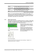
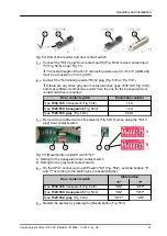
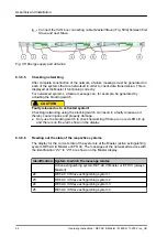
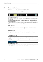
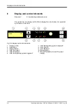
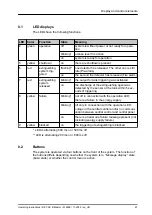
Fig. 54: End-of-line resistor and door contact switch
1.
Connect the "RJ12 plug" door contact switch (Fig. 53/2) to door contact input
"5" (Fig. 52/5) as per Fig. 53.
The overall length of the RJ12 connecting cable used (0.14 mm
2
(AWG 26))
must be a maximum of 30 m (98 ft).
2.
Connect the "Terminating resistor" RJ12 plug (Fig. 53/3 or Fig. 54/1).
If there are any older, gray door contact switches (type 7320.530, Fig. 54/4),
note that a different end-of-line resistor from the one for the transparent door
contact switches is required:
Door contact switch
End-of-line resistor
Type
7030.128
1 k
Ω
Type
7320.530
,
transparent
1 k
Ω
Type
7320.530
,
gray
22 k
Ω
3.
Remove the pre-fitted end-of-line resistor (Fig. 52/13) when using the "RJ12
plug" door contact switch.
1
2
1
2
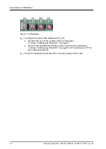
Fig. 55: [Reset] button and DIP switch "S3"
A Setting for the transparent door contact switch
B Setting for the gray door contact switch
4.
On the CPU3 control card on DIP switch "S3" (Fig. 55/2), set slide buttons "6"
and "7" according to the switch type (transparent/gray):
Door contact switch
Slide button
"6"
"7"
Type
7030.128
"ON"
"OFF"
Type
7320.530
,
transparent
"ON"
"OFF"
Type
7320.530
,
gray
"OFF"
"ON"
5.
Restart the system by pressing the
[Reset]
Assembly and installation
Operating Instructions / DET-AC III Master / 916005 / 11-2022 / en_US
57


