19
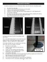
ADJUSTING THE RIP FENCE FOR DRIFT
The 10-324TG Bandsaw can be adjusted to eliminate
‘drift’ - bringing the fence back to being parallel to the
blade - by two methods. To adjust the fence for drift:
Method 1. Loosen the two Hex Screws (#10F) which
hold the Rip Fence (#1F) to the Fence Carrier (#6F).
Adjust the fence so that is parallel to the blade/miter
gauge slots, then re-tighten the hex screws.
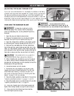
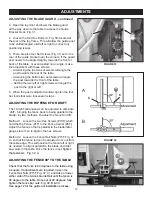
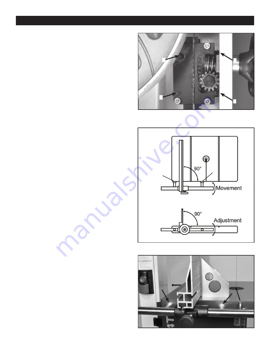
Method 2. Loosen the Fence Rail Nuts (#15F, Fig. 32
C) so that the fence rail can be adjusted in or out from
the table edge. This will position the fence left or right,
as needed, to align it parallel to the blade and miter
saw slots in the table. Once the fence is set,
tighten
the fasteners. Fig. 32, A.
ADJUSTMENTS
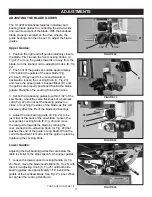
FIGURE 32
ADJUSTING THE BLADE GUARD - continued
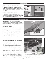
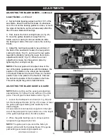
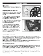
3. Open the top door and lower the blade guard
all the way down to the table to access the Guide
Bracket block. Fig. 31.
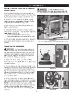
4. Loosen the four Hex Bolts (C, Fig. 30) located at
the rear of the top frame. This will allow the guide post
to be shifted/angled a bit left or right to correct any
positioning issues.
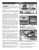
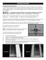
5. There are also four Set Screws (Fig. 31) set in the
rear of the guide bracket near the corners. If the guard
post needs to be angled slightly towards the front or
back of the table, or even twisted on an angle, make
the adjustment with these screws.
- Advancing the top two set screws will angle the
post towards the rear of the table.
- Advancing the bottom two set screws will angle
the post towards the front of the table.
- Setting the two left or right screws will angle the
post to the right or left.
6. When the post is adjusted vertical, tighten the four
hex bolts that were loosened in step 4.
FIGURE 31
ADJUSTING THE FENCE 90° TO THE TABLE
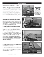
Check that the fence is 90 degrees to the table using
a square. If adjustments are required,
loosen the
Fence Rail Nuts (#15F, Fig. 32, C) and
raise or lower
either side of the fence’s Guide Rail until the fence is
90 degree to the table. Once set at 90 degrees, fully
tighten the fence bar nuts. Fig. 32, B & 33.
See page 12 for the guide rail installation process.
FIGURE 33
90°
B
A
B
C
C
1
2
3
4
Содержание 10-324TG
Страница 43: ...43 OPERATION...

