background image

7 Maintenance


7-2. Regular maintenance mode 


- 60 - 


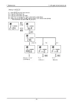
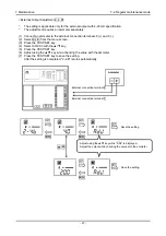
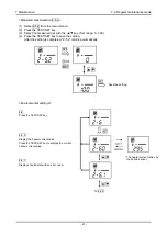
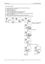
<Heater Current Adjustment 2-5. 0> 


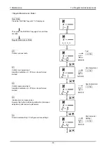
(1)   Select 2-5.0 from the menu screen.   
(2)   Press the TEST/SET key. 
(3)   The heater current is adjusted automatically. 
(4)   After the adjustment, press the TEST/SET key to return to "2-5.0".   


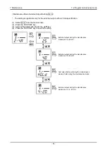
 CAUTION 


Execute this before performing calibration (zero/span adjustment) after sensor replacement. 


After cycling the power or recovering from a blackout and so on, always perform zero 
calibration after making sure that a gas to be detected is not present around the unit. 


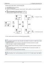
When "E-1" is displayed after initial clear, cycle the power or perform heater adjustment in the 
maintenance mode "2-5.0".   

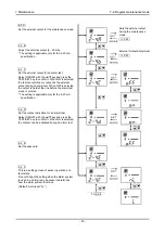
Success 

Fail 

Return to "2-5.0".   

Return to "2-5.0".   

* The heater current varies by 

the built-in sensor. 

Содержание GP-147

Страница 1: ...PT1E 1110 Combustible Gas Detection Alarm System GP 147 Operating Manual ...

Страница 2: ...alarm system 27 5 4 Detection mode 28 5 5 Gas test mode 32 5 6 Alarm test mode 33 5 7 Simplified calibration zero span adjustment 34 5 8 UPS unit operation for the case of UPS specification 36 5 9 How to exit 38 6 Operations and Functions 39 6 1 Gas alarm activation 39 6 2 Fault alarm activation 40 6 3 Gas alarms triggered by a factor unrelated to gas detection 41 6 4 Other functions 41 7 Maintena...

Страница 3: ...ive qualitative analysis measurement for gases Please fully understand the features of the alarm system before using it so that it can be used properly A combustible gas that leaked into the air is detected by a combustible gas detector head connected to the indicator alarm system As a detection result gas concentration is displayed on the LCD bar meter display green and red Gas concentrations are...

Страница 4: ...his message indicates that improper handling may cause serious damage on life health or assets WARNING This message indicates that improper handling may cause serious damage on health or assets CAUTION This message indicates that improper handling may cause minor damage on health or assets NOTE This message indicates advice on handling ...

Страница 5: ...2 Important Notices on Safety 2 1 Danger cases 5 2 Important Notices on Safety 2 1 Danger cases DANGER This is not an explosion proof unit ...

Страница 6: ...tective functions is suspected do not operate the alarm system Fuse To prevent fire use a fuse with the specified ratings current voltage and type for the alarm system Turn the POWER switch OFF and cut the mains power before replacing a fuse Do not use an unspecified fuse or short circuit the fuse holder Operation in a gas Do not operate the alarm system in a place where combustible explosive gase...

Страница 7: ...ses static electricity and electromagnetic noises This is an electrical appliance When the alarm system is used in an environment where electrical noises static electricity or electromagnetic noises may be generated take a protective measure beforehand Do not modify the alarm system or change the settings if not necessary Disassembling modifying the alarm system will invalidate the warranty of the...

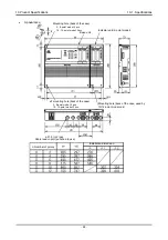
Страница 8: ...le back of the case 2 8 point model 2 pcs 10 12 point model 3 pcs Base unit Indicator unit 2 point model Mounting hole back of the case used by 10 12 point model only ø21 5 n 2 pcs Cable lead in port punched to use ø7 mounting hole back of the case 2 8 point model 2 pcs 10 12 point model 3 pcs ...

Страница 9: ...ndicator unit consists of an indicator part 2 point model In addition to the indicator part the base unit incorporates a switching regulator and UPS uninterruptible power system battery For the case of UPS specification Appearance P P1 P2 2 305 297 276 4 395 387 366 6 485 477 456 8 575 567 546 10 665 657 302 334 12 755 747 308 418 点数n W W1 取付寸法 n Number of points Installation dimension Base unit I...

Страница 10: ...3 Product Functions 3 2 Product components and names 10 Inside Base Unit UPS battery Switching regulator Pump switch Power switch Voice unit option Japanese only Connector CN6 6P ...

Страница 11: ... Rack mounting type n Number of points 2 8 point 4 pcs 10 12 point 6 pcs n 2 1 pcs Rear cable lead in port Installation dimension Installation Diagram for Wall Mounting Type n Number of points Number of points n Cut hole dimension A Panel Cut for Rack Mounting Type n Number of points M6 or ø7 ...

Страница 12: ...CK switch Operated when a battery discharge test is conducted Turn ON for over 3 seconds 5 Alarm lamp Lights up in red at a gas alarm state It goes out when the alarm is cleared 6 Buzzer Emits a buzzer sound at an alarm or fault state 7 BZ STOP switch Stops a buzzer sound 8 RESET switch Pressed to reset the gas alarm activation While the alarm pattern is self latching pressing the RESET switch cau...

Страница 13: ... key Used to enter the alarm test mode Confirms a value etc in each mode 9 POWER switch Power switch of each channel 10 Maintenance mode selector switch MAINT switch Used to switch to the target channel for zero or span adjustment 11 Individual alarm contact output 2 Used as either gas alarm contact or fault alarm contact Gas alarm contact used as standard 12 Individual alarm contact output 1 Used...

Страница 14: ...el display Controller Power supply Alarm processing part Common alarm contact Voltage output 0 6 12 VDC 24 V External buzzer contact CH1 AMP Switching regulator Controller CH2 AMP UPS battery 12 V 2 3 A x 2 Alarm processing part external signal processing Individual alarm contact 0 6 12 V or 4 20 mA Power input 100 120 VAC 200 240 VAC 50 60 Hz Detector head sensor Detector head sensor ...

Страница 15: ...to Use 4 1 Before using the alarm system Not only the first time users but also the users who have already used the alarm system must follow the operating precautions Ignoring the precautions may damage the alarm system resulting in inaccurate gas detection ...

Страница 16: ...ocks and risk of drop etc Keep the alarm system and its cables away from noise source devices When selecting installation points avoid a place where high frequency devices exist Do not place the alarm system next to a noise source device Do not run cables parallel to each other Do not place cables close to each other Do not install the alarm system in a place where detectable gases stay around Do ...

Страница 17: ...ming from the outside lightning will cause problems Because lightning acts as a large emission source while cables act as a receiving antenna devices connected to the cables may be damaged Lightning cannot be prevented Cables installed in a metal conduit or under the ground cannot be completely protected from inductive lightning surge caused by lightning Protection against lightning Although compl...

Страница 18: ...ernal relay at a lower voltage of 100 VAC or below contact amplification At the same time the surge absorbing part SK1 suitable for the specifications must be attached to the external relay In addition the surge absorbing part SK2 must be attached to the loaded side of the external relay if necessary It may be recommended that the surge absorbing part should be attached to the contact for certain ...

Страница 19: ...ay low voltage relay Alarm contact WARNING Before turning on the alarm system never fail to connect the earth terminal to a grounding terminal Terminal For stable operation of the alarm system and safety it must be connected to a grounding terminal Never connect the grounding wire to a gas pipe The grounding must be made as D type grounding below 100 Ω of grounding resistance ...

Страница 20: ...s caught by the upper door which may be closed by shaking the main unit hard during installation 10 12 point Model Screw each four fixing screw to the four corners and two points of the indicator unit next to the base unit six areas in total Be careful not to get your fingers caught by the upper door which may be closed by shaking the main unit hard during installation Mounting hole 4 areas Mounti...

Страница 21: ...them Be careful not to get your fingers caught by the upper door which may be closed by shaking the main unit hard during installation 3 After screwing the mounting brackets B at four areas or six areas according to the above step 2 tighten the screws to complete the installation There are four areas to screw the mounting brackets for the 4 8 point model and six for the 10 12 point model as with t...

Страница 22: ...put The indicator unit outputs the individual alarm contact 1 gas alarm contact and individual alarm contact 2 gas alarm contact or fault alarm contact Also the base unit outputs the common alarm contact and external buzzer contact The contact capacity is 250 VAC 2 A for the common alarm contact and 250 VAC 1A for the external buzzer contact Both are resistance loads Configure an auxiliary relay c...

Страница 23: ...ontact output no voltage c contact contact capacity 250 VAC 2 A resistance load Contact output for external buzzer contact capacity 250 VAC 1 A resistance load Power output for external buzzer 24 VDC load current 10 mA or less Screw size M3 Not used CH1 left Screw size M3 Individual alarm contact output 2 gas alarm standard or fault alarm option Individual alarm contact output 1 gas alarm External...

Страница 24: ...s detector head cables and signal cables must not be installed together with motor power cables etc Do not use the output for pump power supply for detector head to operate other devices Note that only the pumps with the same voltage specification as the input power of the alarm system can be connected For a pump with a different voltage specification an additional power supply is required 4 5 6 7...

Страница 25: ...hock or damage the alarm system Connect the alarm system to a grounding circuit Check that the external wiring is done properly Check that the power supply voltage is compliant with the specifications Because the external contact may be activated during the adjustment take measures to prevent an activated contact from having influences on external circuits Make sure to use a fuse with the specifie...

Страница 26: ...1 or CH2 or 2 Press the MODE key for over 3 seconds with the MAINT switch at the center Gas test mode Simplified calibration zero span adjustment Alarm setpoint check Press the TEST SET switch Press the MODE key for over 3 seconds Maintenance mode user mode Maintenance mode regular maintenance mode Press the TEST SET key for over 3 seconds 1 Return the MAINT switch to the center or 2 Press the MOD...

Страница 27: ...k of the unit External output 0 6 12 VDC output 6 VDC standard 4 20 mA DC output Approx 2 5 mA option Deactivation of alarms and troubles lamps contacts CAUTION Do not turn off the alarm system during the initial clear If a new sensor is installed or the sensor is replaced after the alarm system is started the sensor must be warmed up for a specified period which is determined depending on the typ...

Страница 28: ...D lamp function according to the unit status Measurement Mode Only the POWER lamp lights up and the bar meter green displays a sampling gas concentration A reading under zero is suppressed with 10 of the full scale If a reading under zero reaches or exceeds 10 of the full scale the bar is lowered by one step from the zero point as shown in the right figure Off ON Blinking Maintenance mode active 0...

Страница 29: ...p blinks in red and the buzzer sounds Also the alarm lamp of the base unit lights up in red Fault Display A fault alarm is triggered when the alarm system detects abnormalities auto reset When a fault alarm is triggered the FAULT lamp lights up in orange an error code appears on the LCD and the buzzer sounds Memory error Generated as a result of self diagnosis at power on Sensor disconnection erro...

Страница 30: ... V 6 Alarm test 12 V 7 Fault alarm 0 V 6 Power Off 0 V 2 4 20 mA output specification option 1 Signal transmission method Electric current transmission non isolated 2 Transmission path CVVS 3 Transmission distance 1 km or less 4 Connection load resistance 300 Ω or less 5 Status signal level 1 Detection mode 4 20 mA depends on the gas concentration 2 Gas alarm 4 20 mA depends on the gas concentrati...

Страница 31: ...e Maintenance mode CAUTION The 4 20 mA output is already adjusted If readjustment becomes necessary after installation it must be done by a qualified service engineer Off ON Blinking Maintenance mode active 1 When the TEST SET key is pressed in the detection mode the current alarm setpoint value is displayed for checking 2 Release the TEST SET key to return to the detection mode This is used to ch...

Страница 32: ...nce mode active lights up at the channel to which the MAINT switch is slid on the LCD and a gas concentration value is displayed digital display Return the MAINT switch to the center to return to the detection mode Method 2 The following figure shows an enlarged view of the indicator part Press the MODE key for over 3 seconds in the measuring mode to put both CH1 and CH2 into the gas test mode At ...

Страница 33: ...eached the ALARM lamp blinks in red and the buzzer sounds alarm contact activation Also the alarm lamp of the base unit lights up in red 1 Press the SET switch for over 3 seconds in the gas test mode to enter the alarm test mode 3 Press the BZ STOP switch to stop the buzzer When the RESET switch is pressed the alarm lamp changes from blinking to steady on to enter the auto reset state When the rea...

Страница 34: ...ibration gas Zero adjustment gas collected in a gas sampling bag Calibration gas collected in a gas sampling bag Gas sampling bag for exhaust gas When a diffusion type detector is connected a pump is required How to Perform Simplified Calibration 1 Slide the MAINT switch to the calibration target channel side WARNING After the adjustment is completed never fail to return to the detection mode Gas ...

Страница 35: ...he reading starts blinking adjust the gas concentration with the key 6 Press the TEST SET key After CAL is displayed gas adjustment is performed automatically When the adjustment is completed PASS is displayed FAIL is displayed when zero adjustment fails Press the TEST SET key and try again 7 Return the MAINT switch to OFF CAUTION Do not press the TEST SET key before the reading is stabilized CAUT...

Страница 36: ...rotection The battery voltage is monitored while the UPS is in operation If it drops to or below 21 V UPS is cut off stopped automatically 5 8 2 Operation at power on 1 Initial clear To avoid false alarms any input from the switches or information from the indicator part or indicator alarm unit is rejected for approximately 25 seconds after power on 5 8 3 Basic functions 1 Power status display fun...

Страница 37: ... or more 1 Steady on Color Red Less than 21 V 1 Blinking Color Red The bar meter is displayed in green for all the cases of 24 V and above 3 Discharge test function The battery performance is checked as follows using the self discharge function 1 Press the BATT CHECK switch for over 3 seconds The BATT VOLTAGE bar meter lights up in green orange and a discharge test is started The POWER lamp lights...

Страница 38: ...Select ON to perform backup in the event of a blackout or select OFF when backup is not required Front Inside 5 9 How to exit To turn off the alarm system open the front cover of the base unit and turn OFF the power switch Then turn off the power supply 100 240 VAC to the alarm system The selector switch for backup is located on the PCB of each indicator unit WARNING When the alarm system is turne...

Страница 39: ...rm setpoint is reached or exceeded the alarm lamp lights up and the ALARM lamp blinks The alarm indicator lamp goes out when the gas concentration falls below the alarm setpoint after Bz STOP reset operation 2 External output operation 1 0 6 12 VDC output standard When an alarm is triggered 12 VDC is output The connectable load is 10 mA or less 2 4 20 mA output option A current proportional to the...

Страница 40: ...ective equipment to avoid dangers and go to the gas leak point and then check if gases remain using a portable gas detector etc 5 Check that the point is free from dangers and take actions to fix the gas leak 6 2 Fault alarm activation Fault alarm Triggered when an abnormality is detected in the alarm system Auto reset applies to the cases other than the system error E 00 When a fault alarm is tri...

Страница 41: ...n Function Some types of detector heads connected to the alarm system are influenced by environmental changes temperature humidity and other characteristics or interference gases interference characteristics in no small measure which affects the reading Therefore the reading might fluctuate around zero even in a normal state with no gas leakage This function obscures influences by environmental ch...

Страница 42: ...tivity variations over time by a program manipulation to stabilize the zero point Peak Hold Function In normal measurement detection mode the peak concentration since an alarm activation is held and displayed on the bar When the full scale is exceeded the FS bar blinks Press BZ STOP and then RESET to release the hold state Zero Follower Off Time Zero point Reading The zero drift of the sensor appe...

Страница 43: ... Inspect the alarm circuit by using the alarm test function Span adjustment Perform the span adjustment by using the calibration gas About Maintenance Services We provide services on regular maintenance including span adjustment other adjustments and maintenance To make the calibration gas dedicated tools such as a gas cylinder of the specified concentration and gas sampling bag must be used Our q...

Страница 44: ...s triggering of alarm when the alarm setpoint is reached Checks the delay time Checks time to delay until the alarm is triggered Checks the alarm lamps Checks the alarm activation Checks the external alarm Checks the activation of the external alarm such as a buzzer Cleaning and repair of unit Checks dust or damage on the surface cover or internal parts of the unit cleans and repairs such parts Vi...

Страница 45: ...ment P57 2 4 C External output setting for alarm test 2 4 D Contact output setting for alarm test 2 4 E Password setting 2 4 F Sensor operation setting at a fault state Environmental setting 2 P58 2 5 Functions setting 2 5 0 Heater current adjustment P60 2 5 1 Not used 2 5 2 Measured gas selection P61 2 5 3 Alarm value limiter setting 2 5 4 Fault delay time setting 2 5 5 Buzzer setting for fault s...

Страница 46: ...s tests 2 1 Perform zero adjustment Simplified calibration P34 can be performed instead 2 2 Perform span adjustment Simplified calibration P34 can be performed instead 2 3 Initialize zero and span values Execute this before performing calibration zero span adjustment after sensor replacement 2 4 Environmental setting 1 Configure various settings Zero Adjustment P62 Span Adjustment P63 Test P48 Env...

Страница 47: ... Environmental setting 2 Configure various settings 2 6 Check various displays heater current fault detail 2 7 Enter the factory mode This is not used by the user 2 8 Return to the user mode 1 0 Environmental Setting 2 P58 Various Settings P61 To 2 0 ...

Страница 48: ...tenance mode 48 Test 2 0 2 0 Press the TEST SET key Fault Alarm Test P49 2 0 1 Not used 2 0 3 Test LED and LCD 2 0 0 Not used 2 0 2 Conduct a fault alarm test 2 0 4 Conduct a memory test LED and LCD Test P49 Memory Test P50 To 2 0 0 ...

Страница 49: ...eturns to 2 0 2 LED and LCD Test 2 0 3 1 Select 2 0 3 from the menu screen 2 Press the TEST SET key 3 Select ON OFF with the key 4 Press the TEST SET key to confirm it 5 Return to 2 0 3 with the MODE key Pressing the MODE key during a test clears the setting and returns to 2 0 3 Clears the setting The unit behaves in the same manner as in the case of a fault All LEDs and LCDs light up Clears the s...

Страница 50: ...ss the TEST SET key 3 Press the TEST SET key again 4 After CAL is displayed a memory test starts automatically 5 If the test is successful PASS appears and 2 0 4 returns automatically If the test fails use the MODE key to return Returns to 2 0 4 automatically F ro ROM error F rA RAM error Success Fail Fail ...

Страница 51: ...OFF with the key and press the TEST SET key to confirm it When ON is selected intermittent operation is performed while UPS is used The standard specification is OFF and continuous operation is performed while UPS is used 2 4 1 Not used 2 4 2 Set the alarm setpoint 2 4 3 Set the alarm delay time Change the value second by pressing the key and then press the TEST SET key to confirm the value Set ra...

Страница 52: ... Set the suppression value Change the value by pressing the key and then press the TEST SET key to confirm the value 2 4 7 Set the individual alarm contact 2 Select AL gas alarm contact FAU fault alarm contact with the key and press the TEST SET key to confirm it 2 4 8 Select either energized de energized for the alarm contact 2 4 9 Set the zero follower Select ON OFF with the key and press the TE...

Страница 53: ...put is held at the one before the alarm test mode is entered The setting is applicable only for the 4 20 mA specification 2 4 D Set the contact activation for an alarm test Select ON OFF with the key and press the TEST SET key to confirm it When ON is selected the contact can be activated during an alarm test 2 4 E Set the password 2 4 F This is a setting screen of sensor operation at a fault stat...

Страница 54: ... the setting is completed 2 4 2 returns automatically Alarm Activation Setting 2 4 4 1 Select 2 4 4 from the menu screen 2 Press the TEST SET key 3 Select L NL with the key 4 Press the TEST SET key to save the setting After the setting is completed 2 4 4 returns automatically CAUTION The alarm setpoint mark appears only when the alarm value is set to 25 of the full scale Self latching is set Save ...

Страница 55: ...ted the relay is energized and activated in response to an alarm de energized at a normal environment When the contact a is used it is open at a normal state while closed in response to an alarm When the contact b is used it is activated conversely When energized is selected the relay is energized at a normal environment de energized in response to an alarm When the contact a is used it is closed ...

Страница 56: ...m the menu screen 2 Press the TEST SET key 3 Select 2 5 4 0 HOLD 4 20 with the key 4 Press the TEST SET key to save the setting External output during the maintenance mode is set to 2 5 mA Last value before entering the maintenance mode is held during the maintenance mode External output during the maintenance mode is set to 4 0 mA External output during the maintenance mode is set to 4 20 mA ...

Страница 57: ...2 4 B from the menu screen 3 Press the TEST SET key 4 Select 4 0 20 0 with the key 5 Press the TEST SET key 6 Adjust using the key while checking the value with the ammeter 7 Press the TEST SET key to save the setting After the setting is completed 2 4 B returns automatically External connection terminal 8 External connection terminal 7 Ammeter Save the setting Adjust using the key while ADJ is di...

Страница 58: ...e settings by mistake 2 5 Select 2 5 from the regular maintenance mode Press the TEST SET key 2 5 0 Adjust the heater current 2 5 1 Not used 2 5 2 Select the measured gas 2 5 3 This is a setting screen of the alarm value limiter Do not change the setting when the alarm system is used in a normal way Default ON 2 5 4 Set the fault delay time Change the value second by pressing the key and then pres...

Страница 59: ...it When ON is selected the buzzer sounds at a fault state 2 5 6 Set the 24 hour zero follower 2 5 7 Adjust the brightness of the LCD backlight green Adjust the value with the key and press the TEST SET key to confirm it 2 5 8 Adjust the brightness of the LCD backlight red Adjust the value with the key and press the TEST SET key to confirm it To 2 5 0 ...

Страница 60: ...te this before performing calibration zero span adjustment after sensor replacement After cycling the power or recovering from a blackout and so on always perform zero calibration after making sure that a gas to be detected is not present around the unit When E 1 is displayed after initial clear cycle the power or perform heater adjustment in the maintenance mode 2 5 0 Success Fail Return to 2 5 0...

Страница 61: ... 100 4 Press the TEST SET key to save the setting After the setting is completed 2 5 2 returns automatically Environmental setting 2 Save the setting 2 6 Press the TEST SET key 2 6 0 Display the heater current value Press the TEST SET key to display the current heater current value 2 6 1 Display a fault detail with an error code To 2 6 0 The heater current varies by the built in sensor ...

Страница 62: ... 1 This is used to perform the zero adjustment on the detector head sensor 1 Select 2 1 from the menu screen 2 Press the TEST SET key 3 After CAL is displayed zero adjustment is performed automatically 4 If the adjustment is successful PASS appears and 2 1 returns automatically FAIL appears when the adjustment fails WARNING Perform zero adjustment using the zero adjustment gas or in a place where ...

Страница 63: ...en the reading is stabilized SET is unavailable below 10 of the full scale 5 When the reading starts blinking adjust the gas concentration with the key 6 Press the TEST SET key 7 After CAL is displayed gas adjustment is performed automatically 8 If the adjustment is successful PASS appears and 2 2 returns automatically Success Fail Returns to 2 2 automatically Return to 2 2 Adjust value with Intro...

Страница 64: ...dures to relocate the alarm system or use it again When the alarm system is relocated select a new place in accordance with 4 2 Precautions for installation sites and 4 5 How to install For information on wiring work see 4 7 Wiring The unpowered time for the detector head sensor or indicator must be minimized when the alarm system is relocated 8 3 Disposal of products When the alarm system is disp...

Страница 65: ... power supply system Provide the rated voltage Take measures such as checking or adding the UPS power supply line filter insulation transformer etc Cable abnormalities disconnection not connected short circuit Check the wiring of alarm system and related devices around it Abnormal operations Disturbances by sudden surge noise etc Turn off and restart the alarm system If such a symptom is observed ...

Страница 66: ... and restart the alarm system If such a symptom is observed frequently take appropriate measures to eliminate the noise Sudden change in the environment When the environment temperature etc changes suddenly the alarm system cannot adjust to it and is affected by it In some cases the alarm system triggers an indication alarm Because the alarm system cannot be used under sudden and frequent environm...

Страница 67: ...nt model Approx 290 H x 305 W x 73 D mm approx 3 9 kg 4 point model Approx 290 H x 395 W x 73 D mm approx 5 0 kg 6 point model Approx 290 H x 485 W x 73 D mm approx 5 8 kg 8 point model Approx 290 H x 575 W x 73 D mm approx 6 6 kg 10 point model Approx 290 H x 665 W x 73 D mm approx 7 4 kg 12 point model Approx 290 H x 755 W x 73 D mm approx 8 2 kg The weight above represents the total weight incl...

Страница 68: ...del 2 pcs 10 12 point model 3 pcs Base unit Indicator unit 2 point model ø7 mounting hole back of the case 2 8 point model 2 pcs 10 12 point model 3 pcs Mounting hole back of the case used by 10 12 point model only ø21 5 n 2 pcs Cable lead in port punched to use n Number of points Installation dimension ...

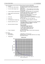
Страница 69: ...pply UPS auto switch on Alarm type Alarm lamp self latching buzzer standard or voice option Japanese only Power input 100 120 VAC or 200 240 VAC 50 60 Hz Use temperature humidity range 10 to 50ºC at a constant condition 10 90 RH non condensing Detection while UPS is used Continuous detection continuous power supply standard or intermittent detection at intervals of 15 seconds intermittent power su...

Страница 70: ...lt alarm option External output signal 2P Alarm delay 2 seconds standard or up to 60 seconds 1 second increment option Other functions Alarm test Alarm activation check Peak gas concentration display When gas concentration exceeds an alarm setpoint the peak value of gas concentration is displayed and held on the bar meter Power Supplied from the base unit Power consumption Max 18 VA 13 W detector ...

Страница 71: ... a result maintenance can be performed on a single unit of the alarm system Initial clear The reading is unstable for seconds after the power is turned on To prevent malfunctions for that period the alarm contact is deactivated In addition a signal to indicate the initial clear status is sent out to the external output Zero suppression A function to cut off the influences of environmental changes ...

Страница 72: ... 6211 3 8 VA D Methane sensor HW 6239 2 8 VA E Hydrogen sensor NC 6244A 1 8 VA F Suction type detector head 33 0 VA 2 Power consumption while running UPS battery W Part Continuous detection Intermittent detection A Base unit Including the indicator unit 1 unit 2 channels 2 8 W 2 8 W B Indicator alarm unit 1 unit 2 channels 2 3 W 2 3 W C Isobutane sensor HW 6211 1 3 W 0 8 W D Methane sensor HW 6239...

Страница 73: ...fusion type mounting all units and 0 LEL Quantity Powered continuously Powered intermittently Isobutane sensor HW 6211 used Isobutane sensor HW 6211 used Power consumption Safety period Power consumption Safety period 2 28 4 VA 5 4 W 600 minutes or more 4 4 W 600 minutes or more 4 36 0 VA 10 3 W Approx 270 minutes 8 3 W Approx 360 minutes 6 43 5 VA 15 2 W Approx 160 minutes 12 2 W Approx 210 minut...

Отзывы: