Rigol DS1000CA series Скачать руководство пользователя страница 138

RIGOL 


  User‟s Guide for DS1000CA Series 

5-6 

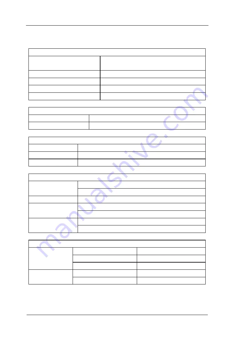
General Specifications 


Display


Display Type 

5.7 in. (145 mm) diagonal TFT Liquid Crystal 
Display 

Display Resolution 

320 horizontal × RGB× 234 vertical pixels 

Display Color 

64k color 

Display Contrast (typical) 

150:1 

Backlight Brightness (typical) 

300 nit 


Probe Compensator Output 

Output Voltage (typical) 

3 Vpp into ≥1 MΩ load 

Frequency (typical) 

1kHz 


Power 

Supply Voltage 

100 ~ 240 VAC

RMS

, 45-440Hz, CAT II 

Power Consumption  Less than 50VA 
Fuse 

2A, T rating, 250 V 


Environmental 

Ambient 
Temperature 

Operating 10

~ 40


Non-operating -20

~ +60


Cooling Method 

Fan force air flow 

Humidity 

+35

 or below: ≤90% relative humidity 

+35

~ +40

: ≤60% relative humidity 

Altitude 

Operating 3,000 m or below 
Non-operating 15,000 m or below 


Mechanical 

Size 

Width 

303mm 

Height 

154mm 

Depth 

133 mm 

Heavy 

Without package 

2.4 kg 

Packaged 

3.8 kg 


Содержание DS1000CA series

Страница 1: ...RIGOL User s Guide DS1000CA Series Digital Oscilloscopes DS1302CA DS1202CA DS1102CA DS1062CA Dec 2009 RIGOL Technologies Inc ...

Страница 2: ......

Страница 3: ...on in this publication replaces all previously corresponding material RIGOL shall not be liable for losses caused by either incidental or consequential in connection with the furnishing use or performance of this manual as well as any information contained Any part of this document is forbidden to copy or photocopy or rearrange without prior written approval of RIGOL Product Certification RIGOL gu...

Страница 4: ...ect The Probe The probes ground terminals are at the same voltage level of the instrument ground Do not connect the ground terminals to a high voltage Observe All Terminal Ratings To avoid fire or shock hazard observe all ratings and marks on the instrument Follow the user s guide for further ratings information before making connections to the instrument Do Not Operate Without Covers Do not opera...

Страница 5: ...Category Definitions Measurement Category I is for measurements performed on circuits not directly connected to MAINS Examples are measurements on circuits not derived from MAINS and specially protected internal MAINS derived circuits In the latter case transient stresses are variable for that reason the transient withstand capability of the equipment is made known to the user WARNING IEC Measurem...

Страница 6: ...could result in damage to this product or other property Terms on the Product These terms may appear on the product DANGER indicates an injury or hazard that may immediately happen WARNING indicates a potential injury or hazard that may immediately happen CAUTION indicates that a potential damage to the instrument or other property might occur Symbols on the Product These symbols may appear on the...

Страница 7: ...aveforms also AUTO button is available to display a signal automatically What s more design of panels LCD interface and buttons are friendly and clear making operation more comfortable Main Features Dual Channel Bandwidth 300MHz DS1302CA 200MHz DS1202CA 100MHz DS1102CA 60MHz DS1062CA Color TFT LCD 320 234 pixels resolution Plug and play USB storage Adjustable waveform intensity more effective wave...

Страница 8: ...ubtract and Multiply Mathematic Functions Advanced trigger types include Edge Video Pulse width Slope Alternative Adjustable trigger sensitivity Multiple Language User Interface Pop up menu makes it easy to read and easy to use Built in Chinese and English help system Easy to use file system supports Chinese English characters file name input ...

Страница 9: ...and the functions and measurements of instrument deeply Chapter 3 Application Examples To show the measurement functions directly by application examples Chapter 4 Troubleshooting Provide you troubleshooting to solve the problems during operating Chpter 5 Specifications List common specifications and characteristics of DS1000CA series oscilloscope Chapter 6 Appendix Information about accessories w...

Страница 10: ...Chapter 2 Operating Your Oscilloscope 2 1 To Set Up the Vertical System 2 2 Channel Settings 2 4 Math functions 2 14 REF function 2 18 To Set Up the Horizontal System 2 25 Delayed Scan 2 27 X Y Format 2 28 To Set Up the Trigger System 2 29 Edge Trigger 2 30 Pulse Width Trigger 2 31 Video Trigger 2 32 Slope Trigger 2 34 Alternative Trigger 2 36 Trigger Settings 2 39 Trigger Holdoff 2 40 To Set Up t...

Страница 11: ...asurements 3 1 Example 2 View a Signal Delay Caused by a Circuit 3 2 Example 3 Capture a Single Shot Signal 3 3 Example 4 To Reduce the Random Noise on a Signal 3 4 Example 5 Making Cursor Measurements 3 6 Example 6 The application of the X Y operation 3 8 Example 7 Triggering on a Video Signal 3 10 Example 8 FFT Cursor Measurement 3 12 Example 9 Pass Fail Test 3 13 Chapter 4 Troubleshooting 4 1 C...

Страница 12: ......

Страница 13: ...Start This chapter covers the following topics General Inspect Panels and User Interface Function Check To Compensate Probes To Display a Signal Automatically To Understand the Vertical System To Understand the Horizontal System To Understand the Trigger System ...

Страница 14: ...he instrument has passed both electrical and mechanical test The consigner or carrier shall be liable for the damage to instrument resulting from shipment without free maintenance or replacement by RIGOL 2 Inspect the instrument In case of any damage or defect or failure notify your RIGOL Sales Representative 3 Check the accessories Accessories supplied with the instrument are listed in Appendix A...

Страница 15: ...CD screen defined No 1 to No 5 are used to switch current menu options Other function buttons are used to enable the access to many measurement features associated with advanced functions mathematics reference or to run control features In addition multi function knob is available to adjust waveform brightness or switch menus but others are applied to adjust offset volts div or s div Figure 1 1 Fi...

Страница 16: ...ost It is used to connect DS1000CA with external USB devices when the oscilloscope is regarded as Host Device For example connect a USB flash device Signal Input Two channels are provided CH1 and CH2 EXT TRIG Input It is applied to input external trigger signal ...

Страница 17: ...control Notation definitions in this User s Guide Throughout this manual notation symbols of buttons and knobs are the same of those on front panel A box around the name of the key denotes MENU function buttons on front panel such as Measure denotes the multi function knob denotes the two POSITION knobs denotes the two SCALE knobs denotes the LEVEL knob The name with a drop shadow denotes the menu...

Страница 18: ... 6 User s Interface Figure 1 3 User s Interface Channel 2 Menu Location of Waveform Trigger Point Run Status Window in Memory in Memory CH1 Volts Div CH2 Volts Div Timebase Trigger Offset Channel 1 Status Bar Trigger Point in Waveform Window ...

Страница 19: ...ess the power switch to turn on the instruments waiting until the display shows the waveform window 2 Recall factory setting Press Storage Storage Factory Load to recall factory setting Figure 1 4 Turn on the instrument WARNNING To avoid electric shock be sure the oscilloscope is properly grounded 3 Input a signal to a channel of the oscilloscope Push BNC plug of probe into CH1 BNC connector then ...

Страница 20: ... correct Default probe attenuation scale is 1X Attach the probe tip to the Probe compensator connector and the reference lead to the ground pin Press AUTO within a few seconds a square wave will display approximately 1 kHz 3 V peak to peak Push the OFF button or push the CH1 button again to turn off Channel 1 Push the CH2 button to turn on channel 2 repeat steps above Probe compensator connector G...

Страница 21: ...a proper connection 2 Attach the probe tip to the Probe compensator connector and the reference lead to the ground pin Select CH1 and then press AUTO 3 Check the shape of the displayed waveform Over compensated Correctly Compensated Under Compensated Figure 1 9 Figure 1 7 Waveform compensation 4 If necessary use a non metallic tool to adjust the trimmer capacitor of the probe for the flattest squa...

Страница 22: ... best fit The input signal should be 50Hz or higher and a duty cycle is greater than 1 Please take the following steps 1 Connect a signal to the oscilloscope input channel 2 Press AUTO The oscilloscope will set up VERTICAL HORIZONTAL and TRIGGER controls automatically You also could adjust the controls manually to get the best results if necessary ...

Страница 23: ...o turn off channels please press OFF 2 Set vertical position of waveform display by knob Turning the knob a voltage value is displayed for a short time indicating its value with respect to the ground reference located at the center of the screen Also notice that the ground symbol on the left side of the display moves in conjunction with the knob Measurement hints If the channel is DC coupled measu...

Страница 24: ... key this is especially helpful when the trace position is far out of the screen and want it to get back to the screen center immediately 3 Set vertical Volts div by knob Rotate to change Volts div the change will be displayed in real time at the bottom of interface Besides the Volts div contains two forms Fine and Coarse Coarse Fine Shortcut key The Coarse Fine vertical control can be set by simp...

Страница 25: ...nal horizontal position on waveform window Turning the horizontal knob the waveform will move to left or right and a sign at the left bottom of the screen will vary to show the horizontal position of the waveform Horizontal offset back to 0 shortcut key Press the knob to set the horizontal offset to 0 as a shortcut key this is especially helpful when the trigger point is far out of the screen and ...

Страница 26: ...ou turning the knob 3 Set horizontal s div by knob The horizontal knob changes the sweep speed in a 1 2 5 step sequence and displays the value in the status bar The time base ranges of the DS1000CA series is from 2ns div to 50s div NOTE The speed of horizontal scan varies by different models Delayed Scan Shortcut key To press the knob in the horizontal control area on the front panel is another wa...

Страница 27: ... line and trigger sign will move up and down when you turn the knob and they will disappear about 5 seconds after stop turning knob The trigger level value will change on the screen at the same time you turn the trigger line 2 Press MENU button in the Trigger control A soft button menu appears on the display showing the trigger setting choices as shown in Figure 1 11 Trigger Level to 0 Shortcut Ke...

Страница 28: ...gure 1 11 NOTE The trigger mode slope and source change in conjunction with the status bar on the top right of the screen 3 Press 50 The 50 button sets the trigger level to the center of the signal 4 Press FORCE Starts an acquisition regardless of an adequate trigger signal usually used in Normal or Single trigger mode This button has no effect if the acquisition is already stopped Local Remote co...

Страница 29: ... all of the following exercises to get the most of the powerful measurement capabilities of the oscilloscope If you haven t know the operations above please refers to chapter1 This chapter covers the following topics To Set Up the Vertical System CH1 CH2 MATH REF OFF Vertical Vertical To Set Up the Horizontal System MENU Horizontal Horizontal To Set Up the Trigger System MENU 50 FORCE To Set Up th...

Страница 30: ...n channel is currently selected press OFF will turn it off and the backlight goes off Table 2 1 The Channels menu Channel Mode Settings Status Indicator Channel 1 CH1 ON Selected OFF CH1 yellow letter CH1 black letter No indicator Channel 2 CH2 ON Selected OFF CH2 blue letter CH2 black letter No indicator MATH ON Selected OFF MATH purple letter MATH black letter No indicator All functions applied ...

Страница 31: ...tical knob The vertical control changes the vertical sensitivity of signal waveforms in all channels including MATH and REF If the Volts Div is set to Coarse the waveform scales in a 1 2 5 step sequence from 2 mV to 10 V If the Volts Div is set to Fine it scales to small steps between the coarse settings 3 Channels would be adjustable by the vertical and only when they are selected 4 During the ve...

Страница 32: ...ttings Comments Coupling AC DC GND Block the DC component of the input Signal Pass both AC and DC components of the input signal Disconnect the input signal BW Limit ON OFF Limit the channel bandwidth to 20MHz to reduce display noise Get full bandwidth Probe 1X 5X 10X 50X 100X 500X 1000X Set this to match the probe attenuation factor to make the vertical scale readout correct Digital filter Setup ...

Страница 33: ...tion Volts Div Coarse Fine Define a 1 2 5 sequence To change the resolution to small steps between the coarse settings Invert ON OFF Turn on the invert function Restore to original display of the waveform Unit V A W U Set V A W or U as the unit of vertical channel Input 50Ω 1MΩ Press this key to select the input resistance to 50Ω or 1MΩ NOTE This parameter is for DS1202CA and DS1302CA only ...

Страница 34: ...ng AC to set AC coupling It will pass AC component blocks the DC component of the input signal Figure 2 3 AC coupling setting Press CH1 Coupling DC to set DC coupling It will pass both AC and DC components of the input signal Figure 2 4 DC coupling setting DC Coupling Setup DC Coupling Status Symbol AC Coupling Setup AC Coupling Status Symbol ...

Страница 35: ...RIGOL User s Guide for DS1000CA Series 2 7 Press CH1 Coupling GND to set GND coupling it disconnects the input signal Figure 2 5 GND coupling setting GND Coupling setup GND Coupling Status Symbol ...

Страница 36: ...OFF to set up bandwidth limit to OFF status The oscilloscope is set to full bandwidth and passing the high frequency component in the signal Figure 2 6 Turn off the BW limit Press CH1 BW Limit ON to set up bandwidth limit to ON status It will reject the frequency component higher than 20MHz Figure 2 7 Turn on the BW limit Turn Off the BW Limit Mark of BW Limit 20M BW Limit ...

Страница 37: ...ck the probe attenuation setting press the CH1 or CH2 button according to which channel in using Toggle the Probe soft button to match the attenuation factor of the probe This setting remains in effect until changed again Figure 2 8 show an example for using a 1000 1 probe and its attenuation factor Figure 2 8 Setting probe attenuation Table 2 4 Probe setting Probe attenuation factors Correspondin...

Страница 38: ...0CA Series 2 10 4 Digital Filter Press CH1 Digital filter display the digital filter menu Figure 2 9 Turn off digital filter Figure 2 10 Turn on digital filter Turn off Digital Filter Mark of Digital Filter Turn on Digital Filter ...

Страница 39: ...r Off On Turn off the digital filter Turn on the digital filter Filter Type Setup as LPF Low Pass Filter Setup as HPF High Pass Filter Setup as BPF Band Pass Filter Setup as BRF Band Reject Filter Upper limit frequency Turn knob to set high limit Lower limit frequency Turn knob to set low limit Back to higher level menu The followings are the same no more explanation ...

Страница 40: ...lts Div in a 1 2 5 step sequence from 1mV div 2mV div 5mV div 10mV div to10 V div Fine This setting changes the vertical scale to small steps between the coarse settings It will be helpful to adjust the waveform in smooth steps Figure 2 12 Fine configurations Coarse Fine Shortcut key To change Coarse Fine setting not only by menu but also by pressing vertical knob Fine Adjustment Fine Adjustment D...

Страница 41: ... degrees as respect to the ground level When the oscilloscope is triggered on the inverted signal the trigger is also inverted Figure 2 13 and 2 14 show the changes before after the inversion respectively Figure 2 13 The waveform before inversion Figure 2 14 The waveform after inversion Invert Off Invert On ...

Страница 42: ...orm of channel1 is marked yellow waveform of channel2 is marked blue and waveform of channel1 adding channel2 is marked purple Figure 2 15 The Math function Figure 2 16 Table 2 6 The Math menu Menu Settings Comments Operation A B A B A B FFT Add source A and source B Subtract source B from source A Multiply source B by source A Fast Fourier Transform Source A CH1 CH2 Define CH1 or CH2 as source A ...

Страница 43: ... Fourier Transform Source CH1 CH2 Define CH1 or CH2 as FFT source Window Rectangle Hanning Hamming Blackman Select window for FFT Display Split Full screen Display FFT waveform on half screen Display FFT waveform on full screen Scale VRMS dBVRMS Set VRMS as vertical unit Set dBVRMS as vertical unit Key points for FFT 1 Signals that have a DC component or offset can cause incorrect FFT waveform com...

Страница 44: ...need to be selected according to measuring waveform Table 2 8 FFT Windows Window Features Best for measuring Rectangle Best frequency resolution worst magnitude resolution This is essentially the same as no window Transients or bursts the signal levels before and after the event are nearly equal Equal amplitude sine waves with fixed frequencies Broadband random noise with a relatively slow varying...

Страница 45: ... points the lower sampling rate results in better resolution Nyquist Frequency The highest frequency that any real time digitizing oscilloscope can acquire without aliasing It s normally half of the sample rate This frequency is called the Nyquist frequency Frequency above the Nyquist frequency will be under sampled causing a situation known as aliasing ...

Страница 46: ... REF channel Select MATH FFT as REF channel Location Internal External Select memory location in scope Select memory location out scope Save Save REF waveform Imp Exp Go to import export menu see table 2 11 Reset Reset REF waveform Figure 2 19 Table 2 10 REF menu when using external memory Menu Settings Comments Source CH1 CH2 MATH FFT Select channel1 as REF channel Select channel2 as REF channel ...

Страница 47: ...d go to the following interface Figure 2 20 Import of export the figure Figure 2 21 Table 2 11 The Imp Exp menu Menu Settings Comments Explorer Path Directory File Switch to Path directory or file Export Export the REF file from internal memory to export memory see table 2 12 Import Import the REF file to internal memory Delete File Delete file ...

Страница 48: ...mory and select Internal location Then press REF Imp Exp Export and go to the following interface Figure 2 22 Figure export Figure 2 23 Table 2 12 The Export menu Menu Settings Comments Move the cursor up Move the cursor down To delete chosen letter Save Execute the operation ...

Страница 49: ... Then press REF Save and go to the following interface Figure 2 24 Save the figure Figure 2 25 Table 2 13 The Save menu Menu Settings Comments Explorer Path Directory File Switch among Path Directory and File New File Folder Set up new file in Path and File Set up new folder in directory Delete File Folder Delete file Folder ...

Страница 50: ...F Save New File or New Folder and go to the following interface Figure 2 26 Input interface Figure 2 27 Table 2 14 The New File menu Menu Settings Comments Move the cursor up Move the cursor down To delete chosen letter Save Execute the operation Character Window Switch Capital On Off Switch Chinese English Spell Key In File Name Key In ...

Страница 51: ... select External location Then press REF Import and go to the following interface Figure 2 28 Figure import Figure 2 29 Table 2 15 The Import menu Menu Settings Comments Explorer Path Directory File Switch among Path Directory and File Import Import the REF file into internal memory ...

Страница 52: ...how the reference waveform menu 2 Press soft button 1 to select the reference channel CH1 CH2 MATH FFT 3 Turn vertical and vertical to adjust the REF waveform to a suitable position 4 Press soft button No 2 to select the save location of REF waveform 5 Press soft button No 3 to save the waveform as REF NOTE The Reference function is not available in X Y mode ...

Страница 53: ...rom right to left Trig offset Reset Reset Adjust to the center NOTE 1 No trigger or horizontal offset control of waveforms is available during Roll Mode and it s only available when set to 500ms div or slower Term Explanations Slow Scan Mode This mode is available when the horizontal time base is set to 50ms or slower In this mode the oscilloscope acquires sufficient data for the left part to the ...

Страница 54: ...es the displayed waveform position relative to the trigger point 1 Horizontal knob is used to adjust the horizontal position of all channel include Math waveforms The resolution of this control varies with the time base Pressing this button clears trigger offset and moves the trigger point to the horizontal center of the screen 2 Horizontal is used to select the horizontal time div scale factor fo...

Страница 55: ...w Figure 2 32 Delayed Scan windows The screen splits into two parts as above The upper half displays the main waveform window and the lower half displays an expanded portion of the main waveform window This expanded portion of the main window is called the Delayed Scan window Two blocks shaded at the upper half the un shaded portion is expanded in the lower half The horizontal and knobs control th...

Страница 56: ... Y mode Figure 2 33 X Y display format The oscilloscope could capture waveform with arbitrary sample rate in Y T mode 2GSa s maximum for single channel 1GSa s maximum for double channels While in X Y mode the sample rate is up to 500MSa s Generally the sample rate is more lower the Lissajous graphics is more better The following modes or functions will not work in X Y format Cursor Measurements Pa...

Страница 57: ...After it detects a trigger the oscilloscope continues to acquire enough data so that it can draw the waveform to the right of the trigger point Press MENU button to enter trigger system setting interface Figure 2 34 Trigger controls DS1000CA provides five trigger modes Edge Pulse Slope Video and Alternative Edge An edge trigger occurs when the trigger input passes through a specified voltage level...

Страница 58: ...17 The Trigger menu Menu Settings Comments Source CH1 CH2 EXT EXT 5 AC Line Select CH1 as trigger signal Select CH2 as trigger signal Select EXT TRIG as trigger signal Select attenuated EXT TRIG 5 as trigger signal Select power line as trigger signal Slope Trigger on rising edge Trigger on falling edge Trigger on both ring falling edge Sweep Auto Normal Single Acquire waveform even no trigger occu...

Страница 59: ...When Set Pulse width as pulse width less than Set Pulse width as pulse width more than Set Pulse width as pulse width equal to Set Pulse width as pulse width less than Set Pulse width as pulse width more than Set Pulse width as pulse width equal to Settings Width Set required pulse width Figure 2 37 Table 2 19 The Trigger menu Page 2 2 Menu Settings Comments Sweep Auto Normal Single Acquire wavefo...

Страница 60: ...gers on negative going sync pulses Triggers on positive going sync pulses Sync All Lines Line Num Odd field Even field Trigger on all lines Trigger on an specified line Select to trigger on odd field Select to trigger on even field Figure 2 39 Table 2 21 The Video Trigger menu Page 2 2 when Sync is set as the specified line Menu Settings Comments Standard PAL SECM NTSC Select Video standard Sweep ...

Страница 61: ...inverted Polarity Select Line Synchronization Select Filed Synchronization Figure 2 41 Figure 2 42 Video Trigger Line Synchronization Video Trigger Field Synchronization Menu Settings Comments Standard PAL SECAM NTSC Select Video standard Sweep Auto Normal Single Force the oscilloscope to trigger in the absence of trigger condition Lets oscilloscope to trigger in the suitable trigger condition Let...

Страница 62: ...dition as slope more than Set slope condition as slope less than Set slope condition as slope equal to Set slope condition as slope more than Set slope condition as slope less than Set slope condition as slope equal to Time Time Set Set slope time Figure 2 44 Table 2 24 The Slope Trigger menu Page2 2 Menu Settings Comments Vertical Select the level that can be adjusted by Sweep Auto Normal Single ...

Страница 63: ...e for DS1000CA Series 2 35 NOTE Slope time can be set from 20ns to 10s When a signal meets the trigger condition scope will execute the acquisition You can adjust LEVEL A LEVEL B or both simultaneous by turning the knob ...

Страница 64: ...Edge Menu Settings Comments Select CH1 CH2 Set trigger mode for Channel 1 Set trigger mode for Channel 2 Type Edge Set Edge Trigger as the trigger type Slope Trigger on rising edge Trigger on falling edge Trigger on both ring falling edge Set Up To go to set up menu See Table 2 32 Figure 2 46 Table 2 26 The Alternative menu Trigger Type Pulse Page 1 2 Menu Settings Comments Select CH1 CH2 Set trig...

Страница 65: ...or Channel 1 Set trigger mode for Channel 2 Type Slope Set Slope Trigger for the vertical channel When Set slope condition as slope more than Set slope condition as slope less than Set slope condition as slope equal to Set slope condition as slope more than Set slope condition as slope less than Set slope condition as slope equal to Figure 2 49 Table 2 29 The Alternative menu Trigger Type Slope Pa...

Страница 66: ...ity Trigger on negative going sync pulses Trigger on positive going sync pulses Figure 2 51 Table 2 31 The Alternative menu Trigger Mode Video Page 2 2 Menu Settings Comments Sync ALL lines Line Num Odd field Even field Trigger on all lines Trigger on an specified line Select to trigger on odd field or even field Line Num Lines Set Select the specified line number for sync Standard PAL SECM NTSC S...

Страница 67: ...upling trigger sensitivity and holdoff Figure 2 53 Table 2 33 The Trigger Set Up menu Settings for sensitivity and holdoff Menu Settings Comments Sensitivity Sensitivity Setting Set trigger sensitivity Holdoff Holdoff Setting Set time slot before another trigger event Holdoff Reset Reset Holdoff time to 500ns Menu Settings Comments Coupling DC AC HF Reject LF Reject Allow all signals pass Block DC...

Страница 68: ...doff ends For instance To trigger on the first pulse on a group of them users can set the holdoff time to Pulse cluster width Figure 2 54 Trigger Holdoff Operation Explanations 1 Press the trigger MENU button to display the Menu 2 Press Set Up key to display trigger set up menu 3 Turn the multi function knob to change Holdoff time until waveform is stable 4 Pushing Trigger Hold off reset to reset ...

Страница 69: ...which extends the trigger level range to 8 V to 8 V allowing the oscilloscope to trigger on a larger signal AC Line AC power can be used to display signals related to the power line frequency such as lighting equipment and power supply devices The oscilloscope gets triggered on its AC power input an AC trigger signal is not required 2 Sweep Mode The sweep mode determines how the oscilloscope behav...

Страница 70: ...sing to the trigger circuit Coupling types include AC DC LF Reject and HF Reject AC AC coupling blocks DC components DC DC coupling passes both AC and DC components LF Reject LF Reject coupling blocks DC component and attenuates all signal with a frequency lower than 8 kHz HF Reject HF Reject coupling attenuates all signals with a frequency higher than 150 kHz 4 Pre trigger delayed trigger The dat...

Страница 71: ... physical world and get the stable trigger the trigger circuit has adopted Stickiness In DS1000CA series the stickiness is adjustable from 0 1div 1 0div which means when it sets to 1 0div the trigger circuit will not affect any signal with peak peak amplitude less than 1 0div so as to avoid the influence of the noise ...

Страница 72: ...ormal Acquisition mode Average Acquisition mode Peak Detect Acquisition mode Averages 1 2 to 256 Step by 2 N times the power Set average times from 2 to 256 Sampling Real Time Equ Time Real time sampling mode Equivalent sampling mode Sinx x 2 ON OFF Set the insert mode is Sinx or Line Sa Rate 3 Display sampling rate NOTES 1 This function appears when acquisition as Average 2 This function appears ...

Страница 73: ...ect the Average Acquisition This mode would make the screen refresh slower To Avoid signal aliasing select Peak Detect Acquisition Select Real time acquisition to observe the single shot or pulse signals Select Equ Time to observe high frequency repetitive signals Figure 2 57 Signal that contains noise and without average sampling Figure 2 58 Display signal after average sampling ...

Страница 74: ... peak detect acquisition signal contains envelope Key points Stop Acquisition When the scope is acquiring waveforms the waveforms is in a live status when acquisition is stopped frozen waveform will be displayed the position and scale can still be adjusted by vertical control and horizontal control ...

Страница 75: ... good for observing repetitive signals and it is not recommended for single shot or pulse Normal Acquisition Oscilloscope acquires signal by equal time interval Average Acquisition Apply averaging to your signal to remove uncorrelated noise and improve measurement accuracy Reduces random or uncorrelated noise in the signal display The averaged waveform is a running average over a specified number ...

Страница 76: ...s vectors Display waveforms as dots Clear Clear all existing waveforms from screen Persist OFF Infinite Turn off the persistence function The sample points remain displayed until turn the persistence OFF Intensity percentage Set up waveform intensity 0 100 Key points Display type Display type includes Vector and Dot In vectors type oscilloscope connects dots through digital interpolation including...

Страница 77: ...d coordinates Menu Display 1s 2s 5s 10s 20s Infinite Set the time before menu fades away The menu will be hidden after the set time of last button pressing Figure 2 64 Table 2 37 The Display menu Page 3 3 Menu Settings Comments Brightness percentage Set up grid brightness Screen Normal Inverted Set to normal mode Set to invert color display mode Term Explanations Refresh rate It is an important pe...

Страница 78: ...RIGOL User s Guide for DS1000CA Series 2 50 Adjusting waveform intensity Default setup of multi function knob is adjusting waveform intensity ...

Страница 79: ...m Store or recall instrument setups Create or delete bit map files Create or delete CSV files Recall factory setups Internal Go to menu for internal memory operation see Table 2 42 External Go to menu for external memory operation see Table 2 43 Disk Mana Go to disk manage menu see Table 2 44 NOTES 1 The waveform and setups files in internal memory can be saved loaded and deleted While the wavefor...

Страница 80: ...nu CSV storage Menu Settings Comments Storage CSV Create or delete CSV files Data Depth Displayed Maximum Save currently displayed waveform data to CSV file Save the whole waveform data in memory to CSV file Para Save On Off Save the current oscilloscope settings in different format with the same file name External Go to menu for external memory operation see Table 2 43 Disk Mana Go to disk manage...

Страница 81: ...09 Thereinto S in brackets indicates the location has storage file N indicates has not Load Recall waveform files and setup files from the internal memory location Save Save waveform files and setup files to the internal memory location Delete File Delete the files NOTE To ensure the setups being saved properly only after the settings are changed for more than 5 seconds can the user turn off the i...

Страница 82: ...tem Figure 2 72 Table 2 43 The External Memory menu Menu Settings Comments Explorer Path Directory File Switch among Path Directory and File New File Folder To create new file or folder Delete File Folder Delete file Folder Load Recall waveform and setup from USB storage device Current Directory Current Path Files Back to Previous Directory File Information ...

Страница 83: ...u Settings Comments Explorer Path Directory File Switch among Path Directory and File New folder To create new folder same as new files Delete File Delete file Load Recall waveform setup recorded waveform Pass Fail file Figure 2 74 Table 2 45 The Disk Management menu Page 2 2 Menu Settings Comments Rename To rename a file see Table 2 46 Disk info Display disk information ...

Страница 84: ...s 2 56 1 Disk Information Press Storage Disk Mana Diskinfo to go to the disk information interface Figure 2 75 Disk information interface 2 Rename Press Storage Disk Mana Rename to go to the following interface Figure 2 76 Rename the file ...

Страница 85: ...o move the cursor down To delete chosen letter OK Rename the file Key point Factory The oscilloscope has default settings and can be recalled at anytime by user Memory location Specify the memory location to save recall the waveforms and setups Load Recall saved waveforms setups and default settings Save Save waveforms and setups ...

Страница 86: ...he Utility button to show the menu of the settings in the Utility system Figure 2 79 Table 2 47 The Utility menu Page 1 3 Menu Setting Comments I O setting Setup I O configuration Sound ON OFF Turn beeper sound on off Counter OFF ON Turn off Frequency Counter Turn on Frequency Counter Language 简体中文 繁体中文 English 日本語 Français Select languages System Function Setup Button ...

Страница 87: ...cord Setup Waveform Recorder Print set Setup printing Figure 2 81 Table 2 49 The Utility menu 3 3 Menu Settings Comments Self Cal Execute Self calibration Service Go to service menu Preference Go to preference menu Term Explanations Self Cal Oscilloscope will calibrate parameter of vertical system CH1 CH2 and Ext horizontal system and trigger system ...

Страница 88: ...0 I O Setup Press Utility I O setting to go to the following menu Figure 2 82 Table 2 50 The I O Setup menu Menu Display Comments RS 232 Baud 300 38400 Set RS 232 baud rate as 300 2400 4800 9600 19200 or 38400 GPIB 0 to 30 Set the GPIB address ...

Страница 89: ...ser s Guide for DS1000CA Series 2 61 Language The DS1000CA series oscilloscopes have multi language user menu choose as your desire Press Utility Language to select the language Figure 2 83 Language interface ...

Страница 90: ...urn on Pass Fail test Turn off Pass Fail test Source CH1 CH2 Select Pass Fail test on CH1 Select Pass Fail test on CH2 Operate RUN STOP Pass Fail test stopped press to run Pass Fail test running press to stop Msg display ON OFF Turn on Pass Fail information display Turn off Pass Fail information display Figure 2 85 Table 2 52 The Pass Fail menu Page 2 2 Menu Settings Comments Output Fail Fail Pass...

Страница 91: ... Mask y div Set vertical clearance to the waveform 0 04div 4 00div Create Mask Create a test mask according to the above clearance Location Internal External Set the memory location of the mask files Figure 2 87 Table 2 54 The Mask setting menu Page 2 2 When the save as internal memory Menu Settings Comments Save Store created test mask into internal memory Load Recall mask setting file from inter...

Страница 92: ...ave menu Load Go to load menu see Table 2 56 Import Go to import menu The same as REF import menu 2 Mask Setting Press Utility Pass Fail Mask Setting Load to go to the following menu Figure 2 89 Table 2 56 The Load menu Menu Settings Comments Explorer Path Directory File Switch among Path Directory and File Load Recall the specified file NOTE Pass Fail function is unavailable in X Y mode ...

Страница 93: ... to fulfill the function Before connecting to an external circuit make sure the maximum voltage current does not exceed the internal photo MOS relay s rating 400V 100mA DS1000CA series adopts the technique of Optical Isolation and the output device has no polarity and can be used in any circuit within the ratings Figure 2 90 Schematic Diagram of Pass Fail output ...

Страница 94: ...re details about the function please refer to the following introduction 1 OFF It will close all record functions 2 Record To record waveform by selected time interval till the last frame Press Utility Record Mode Record to go to the following menu Figure 2 91 Table 2 57 The Record menu Page 1 2 Menu Settings Comments Mode OFF Record Play back Storage Turn off all recorder functions Select record ...

Страница 95: ...2 93 Table 2 59 The Play Back menu Page 1 2 Menu Settings Comments Operate Run Stop Play stopped press to Start playback Press to stop playing Play mode Set repeat play mode Set single time play mode Interval 1 00ms 20s Set up interval Figure 2 94 Table 2 60 The Play Back menu Page 2 2 Menu Settings Comments Start Frame 1 1000 Set start frame Current Frame 1 1000 Select current frame to be played ...

Страница 96: ...age 1 2 Menu Settings Comments Start Frame 1 1000 Set first frame to be saved End Frame 1 1000 Set last frame to be saved Location Internal external Set up Store location Figure 2 96 Table 2 62 The Storage menu when the save to Internal memory Page 2 2 Menu Settings Comments Save Save recorded waveform to internal memory location Load Recall recorded waveform from internal memory location Imp Exp ...

Страница 97: ...s 2 69 Figure 2 97 Table 2 63 The Storage menu when the save as external memory Page 2 2 Menu Settings Comments Save Go to save menu same as REF save menu Load Go to load menu see Table 2 56 Import Go to import menu Same as REF import menu ...

Страница 98: ...es support external printers Press Utility Print set to go to the following menu Figure 2 98 Table 2 64 The Print Set menu Menu Settings Comments Print Execute print function Inverted ON OFF Invert the color for print Print original color Palette Gray scale Color Set up print color ...

Страница 99: ... any time run this calibration if the ambient temperature changes by 5 or more Before running this procedure make sure that disconnect any probes or cables from all channel inputs otherwise failure or damage to the oscilloscope may occur Then press Utility Self Cal Figure 2 99 The Self Calibration menu NOTE The oscilloscope must have been working or warm up at least 30 minutes before running self ...

Страница 100: ...mation Press Utility Service System Info to display the information of the oscilloscope Product Model Serial No Software version and Installed module of the oscilloscope Follow the prompting message Press RUN STOP Key to Exit the Test to exit this interface 2 Color Test Select Color Test to enter the color test screen the hue saturation brightness or red green and blue components can be adjusted b...

Страница 101: ...screen saver timer Expand Refer Ground Center Set up waveform vertical expand reference Screen Persist Set the Screen waveforms persist or display the last sampling waveforms in stopping moment Skin Classical Modern Tradition Succinct Set up skin style Figure 2 102 Table 2 67 The Preference menu Page 2 2 Menu Display Comments Sticky key Set up sticky state of CH1 CH2 MATH REF Trig Lev and Trig Pos...

Страница 102: ... the signal ground level or the center of the screen When Center is selected the waveform will expand or compress around the center of the display When Ground is selected the channel ground level will remain the same position on the display and waveform will zoom about the ground level Sticky key If sticky feature is turned ON when adjusting positions CH1 CH2 MATH REF Trig Lev and Trig Pos the obj...

Страница 103: ...vershoot Preshoot Freq Period Rise Time Fall Time Delay1 2 Delay1 2 Width Width Duty Duty 10 voltage and 10 timing measurements Press the Measure button to display the menu of the Automatic Measurements settings Figure 2 104 Table 2 68 The Measure menu Menu Settings Comments Source CH1 CH2 Select CH1 or CH2 as source channel for measurement Voltage Select to measure voltage parameter Time Select t...

Страница 104: ...waveform 2 Page 2 for voltage measurements Figure 2 106 Table 2 70 The Voltage Measurement menu Menu Settings Comments Base Measure a flat base voltage of a square waveform Amplitude Measure voltage between Top and Base Average Measure average voltage of a waveform RMS Measure Root Mean Square Voltage of a waveform 3 Page 3 for Voltage Measurements Figure 2 107 Table 2 71 The Voltage Measurement m...

Страница 105: ...ge 2 for Time Measurements Figure 2 109 Table 2 73 The Time Measurement menu Menu Settings Comments Width Measure Pulse Width of a pulse wave Width Measure Pulse Width of a pulse wave Duty Measure Duty Cycle of a pulse wave Duty Measure Duty Cycle of a pulse wave 6 Page 3 for Time Measurements Figure 2 110 Table 2 74 The Time Measurement menu Menu Settings Comments Delay1 2 Measure the signals del...

Страница 106: ...measurement parameters will be displayed on the screen except for Delay1 2 and Delay1 2 3 Select parameters page for measuring select voltage or time parameters pages by pressing soft button as follows Measure Voltage or time Vmax Vmin 4 To get the measured value on the screen select the parameters of interest by pressing the soft button on the right of the menu and read the data on the bottom of ...

Страница 107: ...ed over the entire waveform Vmin The minimum amplitude The most negative peak voltage measured over the entire waveform Vamp Voltage between Vtop and Vbase of a waveform Vtop Voltage of the waveform s flat top useful for square pulse waveforms Vbase Voltage of the waveform s flat base useful for square pulse waveforms Overshoot Defined as Vmax Vtop Vamp useful for square and pulse waveforms Presho...

Страница 108: ...f the first pulse in the waveform takes to rise from 10 to 90 of its amplitude Fall Time Time that the falling edge of the first pulse in the waveform takes to fall from 90 to 10 of its amplitude Width The width of the first positive pulse in 50 amplitude points Width The width of the first negative pulse in the 50 amplitude points Delay 1 2 The delay between the two channels at the rising edge De...

Страница 109: ...ce as the channel for measuring 2 Track In this mode the screen displays two cross cursors The cross cursor sets the position on the waveform automatically Adjust cursor s horizontal position on the waveform by rotating the multifunctional knob The oscilloscope displays the values of the coordinates on the boxes below the menu 3 Auto Measure This mode will take effect with Automatic Measurements T...

Страница 110: ...e CurA Set CurA effective and adjust it CurB Set CurB effective and adjust it In this mode the oscilloscope measures the Y or X coordinate values of the cursors and the increments between the two cursors To do manual Cursor Measurements please do as the following steps 1 Select the Manual mode for cursor measurement by pressing soft button as Cursor Mode Manual 2 Select the cursors type by pressin...

Страница 111: ...ground level Position of Cursor B Same as above Horizontal space between cursor A and B X Time between cursors 1 X units in Hz kHz MHz GHz Vertical space between cursor A and B Y Voltage between cursors NOTE The values will be automatically displayed on the right upper corner of screen when the cursor function menu is hidden or displaying other menus Term Explanations Cursor Y Cursors Y appear as ...

Страница 112: ...move cursor B horizontally In Track mode the cross cursor is displayed on the waveform under measuring If you move the horizontal position of cursor the horizontal coordinate and vertical coordinate of current point as well as the increments of them will be displayed immediately Note horizontal coordinate represents time value vertical coordinate represents voltage value To do Track mode Cursor Me...

Страница 113: ...ot tracking cursor menu is activated 4 To get measurement values Position of Cursor A Time cursor centered on the midpoint of screen Voltage cursor centered on channel ground level Position of Cursor B Time cursor centered on the midpoint of screen Voltage cursor centered on channel ground level Read the horizontal space between Cursor A and B X Time between cursors units in seconds 1 X units in H...

Страница 114: ...de menu Menu Settings Comments Mode Auto Display the cursors for the current automatic measuring See the following figure There will be no cursor display if no parameters are chosen in Measure menu The oscilloscope could move cursor automatically to measure 20 parameters in Measure menu Figure 2 118 Auto Measure Mode of Cursor Measurement ...

Страница 115: ...e 2 119 Table 2 80 The Auto menu Menu Settings Comments Multi Cycle Press to display multi cycle waveform on the screen Single Cycle Press to display single cycle waveform on the screen Rise Edge Press to display the waveform s rising edge and measure its rise time automatically Fall Edge Press to display falling edge of the waveform and measure fall time automatically of it Cancel Press to cancel...

Страница 116: ...bandwidth Signal Invert OFF Horizontal position Center Horizontal S div Adjust to right position Trigger type Edge Trigger source Find the channel with input signal automatically Trigger coupling DC Trigger voltage Midpoint setting Trigger mode Auto NOTE When measuring small signal the Bandwidth limit will be turned on automatically RUN STOP Run or Stop waveform acquiring NOTE In STOP status the v...

Страница 117: ...display adjust these controls manually to meet the requirements 2 Selecting Automatic Measurements The oscilloscope takes automatic measurements on most signals To measure the frequency and the peak to peak amplitude do these steps as follows 1 Measure peak to peak amplitude Press Measure Source CH1 to set the measurement source Press Voltage Peak Peak to select the peak to peak measurements and t...

Страница 118: ...e by turning the knobs to appropriate ranges for display 3 Press the CH1 button to select Channel 1 and turn the vertical knob to adjust the vertical position of Channel 1 waveform 4 Press the CH2 button to select Channel 2 and turn the vertical knob to adjust the vertical position of Channel 2 waveform 2 Measure the delay time when a signal going through the circuit 1 Auto measuring the delay Pre...

Страница 119: ...lect Single Press Set Up Coupling to select DC 3 Turn the vertical and horizontal knobs to adjust the Volts Div and the Time base in a proper range for the signal 4 Turn the knob to adjust trigger level 5 Press RUN STOP button to start capturing When the trigger conditions are met data appears on the display representing the data points that the oscilloscope obtained with one acquisition This func...

Страница 120: ...igger by setting the Coupling 1 Press the MENU in the Trigger control area 2 Press Set Up Coupling LF Reject or HF Reject HF Reject High frequency reject adds a low pass filter with the 3 dB cut off point at 150 kHz Use HF rejects to remove high frequency noise such as AM or FM broadcast stations from the trigger path LF Reject Low frequency reject adds a high pass filter with the 3 dB cut off poi...

Страница 121: ...w these steps Press soft button as Acquire Acquisition Average Toggle the Averages soft button to select the number of averages that best eliminates the noise from the displayed waveform It can be adjusted from 2 256 See Figure 3 3 Figure 3 3 Signal without noises 2 To reduce the noise it can also be achieved by reducing the intensity of the display NOTE It is normal that the refresh rate will slo...

Страница 122: ...the Peak Frequency of the First Sinc Waveform To measure the ringing frequency at the rising edge of a signal do these steps 1 Press Cursor key to see the Cursor menu 2 Press Mode to set Manual mode 3 Press Type to select X 4 Turn knob to place cursor A on the first peak of the wave 5 Turn knob to place cursor B on the second peak of the wave Figure 3 4 Waveform display Observe the delta in time a...

Страница 123: ...Press Mode to set Manual mode 3 Press Type to select Y 4 Turn knob to place cursor A on the first peak of the wave 5 Turn knob to place cursor B on the second peak of the wave Observe the following measurements in the cursor menu See Figure 3 5 The delta voltage peak to peak voltage of the waveform The voltage at Cursor 1 The voltage at Cursor 2 Figure 3 5 Waveform display ...

Страница 124: ... to the input of the network and connect the CH 2 probe to the output 3 If the channels are not displayed press the CH1 and CH2 buttons 4 Press the AUTO button 5 Adjust the vertical knob to display approximately the same amplitude signals on each channel 6 Press the MENU in horizontal control area to display the menu 7 Press the Time Base soft button to select X Y The oscilloscope displays a Lissa...

Страница 125: ...ase shift in degrees between the two signals From the formula above you could get arcsine A B or arcsine C D If the main axis of the ellipse is at I and III quadrant must be in the range of 0 π 2 or 3π 2 2π If the main axis is at II and IV quadrant must be in the range of π 2 π or π 3π 2 A B C D Signal must be centered in X ...

Страница 126: ...the Trigger menu 2 Press Mode to select Video 3 Press Source to select CH1 as trigger source 4 Press Polarity to select 5 Press Sync as Odd Field or Even Field 6 Adjust the to set trigger level at the video sync pulse to get stable trigger 7 Turn the horizontal knob to see a complete waveform on the screen Figure 3 7 Waveform display DS1000CA series triggers on the Odd field or Even field To avoid...

Страница 127: ...ode to select Video 3 Press Source to select CH1 as trigger source 4 Press Polarity to select 5 Press Sync to select Line Num 6 Turn knob to trigger on a specified line number 7 Adjust the to set trigger level at the video sync pulse to get a stable trigger 8 Turn the horizontal knob to observe a complete waveform on the screen Figure 3 8 Waveform display ...

Страница 128: ...plitude measurement VRMS or dBVRMS and Frequency measurement Hz Do these steps as follow 1 Press Cursor Manual 2 Press Type to select X or Y 3 Press Source to select FFT 4 Turn knob to move the cursor to an point of interest Figure 3 9 Cursor amplitude measurement Figure 3 10 Cursor frequency measurement ...

Страница 129: ...a programmable output can be used for external automatic control applications The output is built in as a standard feature and is optically isolated Do the steps as following 1 Press Utility Pass Fail 2 Press Enable Test and select ON 3 Press Mask Setting Load 4 Press Load to recall the saved mask or press X Mask and Y Mask to adjust the horizontal limit and vertical limit then press Create Mask t...

Страница 130: ......

Страница 131: ...e object being tested 4 Check if the circuit can generate signal at the test point Connect the probe compensator output to an input channel to confirm whether the testing point has no signal or the input channel is in some troubles 5 Repeat the acquisition 3 The measurement result is 10 times higher or lower than the value expected Check if the probe attenuation is the same as the channel attenuat...

Страница 132: ...rigger Mode as AUTO Moreover push AUTO button to display the waveform on screen 6 After the Acquisition is set to Averages or Display Persistence is set ON the waveform refreshes slowly It is normal in these settings 7 The signal is displayed as ladder like waveform 1 The time base maybe is too low Turn the horizontal knob to increase horizontal resolution to improve the display 2 Maybe the displa...

Страница 133: ...To meet these specifications two conditions must first be met The instrument must have been operating continuously for thirty minutes within the specified operating temperature Must perform the Self Cal operation accessible through the Utility menu if the operating temperature changes by more than 5 All specifications are guaranteed unless noted typical ...

Страница 134: ...tage 300V DC AC Peak 1MΩ input impedance 10X 5V VRMS 50Ω input impedance BNC 3 Time delay between channel typical 500ps 50Ω With DS1302CA DS1202CA Without DS1062CA DS1102CA Horizontal Sample Rate Range 1Sa s 2GSa s Real Time 50GSa s Equivalent 2 Waveform interpolation Sin x x Record Length Up to 10k samples for single channel at 2GSa s 5k samples for each channel Scan speed Range Sec div 1ns div 5...

Страница 135: ... Delay1 2 Delay1 2 Vertical A D converter 8 bit resolution each channel samples simultaneously Volts div Range 1mV div 10V div at input BNC Offset Range 40V 205mV div 10V div 800mV 1mV div 200mV div Analog Bandwidth 60MHz DS1062CA 100MHz DS1102CA 200MHz DS1202CA 300MHz DS1302CA Single shot Bandwidth 60MHz DS1062CA 100MHz DS1102CA 200MHz DS1202CA 300MHz DS1302CA Selectable Analog Bandwidth Limit ty...

Страница 136: ... ambient conditions DC Gain Accuracy reading 0 05 div Overshoot 20 Trigger Trigger Sensitivity 0 1div 1 0div adjustable Trigger Level Range Internal 6 divisions from center of screen EXT 1V EXT 5 3V Trigger Level Accuracy typical applicable for the signal of rising and falling time 20ns Internal 0 3div V div 4 divisions from center of screen EXT 6 of setting 40 mV EXT 5 6 of setting 200 mV Trigger...

Страница 137: ...igger condition Positive slope negative slope Time setting 20ns 10s Alternate Trigger Trigger on CH1 Edge Pulse Video Slope Trigger on CH2 Edge Pulse Video Slope NOTES 1 Only one input channel is available when Sample rate is at 2GSa s 2 This is the highest specification the specific specifications are as follows DS1302CA 50GSa s DS1202CA DS1102CA 25GSa s DS1062CA 10GSa s 3 For DS1202CA and DS1302...

Страница 138: ...Output Voltage typical 3 Vpp into 1 MΩ load Frequency typical 1kHz Power Supply Voltage 100 240 VACRMS 45 440Hz CAT II Power Consumption Less than 50VA Fuse 2A T rating 250 V Environmental Ambient Temperature Operating 10 40 Non operating 20 60 Cooling Method Fan force air flow Humidity 35 or below 90 relative humidity 35 40 60 relative humidity Altitude Operating 3 000 m or below Non operating 15...

Страница 139: ...RIGOL User s Guide for DS1000CA Series 5 7 IP Protection IP2X Calibration Interval The calibration interval is one year ...

Страница 140: ......

Страница 141: ... power switch is in 1X This probe fit bandwidth upper limit which belongs to 300V CATII when the power switch is in 10X A Power Cord that fits the standard of destination country Resource CD including User s Guide Optional Accessories DS1000CA soft carrying case BNC Cable RS 232 Cable USB Cable USB GPIB Adapter 50Ω Impedance Adapter All accessories standard and optional are available by contacting...

Страница 142: ...o get repair service or obtain a copy of the whole warranty statement please contact with your nearest RIGOL sales and service office RIGOL do not provide any other warranty items except the one being provided by this summary and the warranty statement The warranty items include but not being subjected to the hint guarantee items related to tradable characteristic and any particular purpose RIGOL ...

Страница 143: ...ty Cleaning Clean the instrument and probes often based on its operating conditions require To clean the exterior surface perform the following steps 1 Disconnect the instrument from all power sources 2 Clean the loose dust on the outside of the instrument and probes with a lint free cloth with a mild detergent and water When clean the LCD take care to avoid scarifying it WARNING To avoid injury r...

Страница 144: ...ase call Tel 86 10 8070 6688 Fax 86 10 8070 5070 Service Support Hotline 800 810 0002 9 00 am 5 00 pm from Monday to Friday Or by e mail service rigol com Or mail to RIGOL Technologies Inc 156 CaiHe Village ShaHe Town ChangPing District Beijing China Post Code 102206 Overseas Contact the local RIGOL distributors or sales office For the latest product information and service visit our website www r...

Страница 145: ...se Fine 1 13 Cursor 2 81 Cursor Measurements 2 81 D DC Coupling 2 6 Display 5 6 Display System 2 48 E Edge Trigger 2 30 Envelope 2 47 Equivalent Sampling 2 47 Ext and Ext 5 2 41 F Factory Setup 2 57 FFT 2 15 FORCE 1 17 Front panel 1 3 Functional check 1 8 G GND Coupling 2 7 H Hamming Window 2 16 Hanning Window 2 16 HF Reject 2 42 Horizontal 5 2 I I O setup 2 60 Inputs 5 2 Instant Execute Key 2 88 ...

Страница 146: ...rigger 2 31 R Random Noise 3 4 Realtime Sampling 2 47 Rectangle Window 2 16 REF 2 18 RUN STOP 2 88 S Sampling System 2 44 Save and Recal 2 1 Self Calibration 2 71 Single Trigger 2 42 Slope Trigger 2 34 Sync Pulses 2 33 T Trigger 5 4 Trigger Settings 2 39 Trigger System 2 29 U UTILITY 2 58 V Vertical 5 3 Vertical Window 1 12 Video Signal 3 11 Video Trigger 2 32 ...

Отзывы: