Page 7
3.4.7 Cooling system
The INOVAC vacuum pumps are liquid-cooled. There are two cooling
variants.
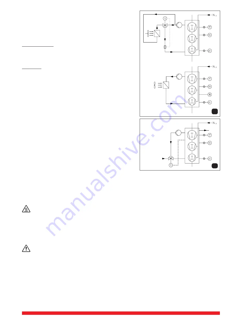
3.4.7.1 Radiator cooling (pict. 9)
With the radiator cooling the medium is circulated, unpressurized in a
closed circuit via a small rotary pump, independent of the coolant tempera-
ture.
VWP 160-3 / 250-3:
When the coolant temperature reaches that set on the thermosensor in
the cooling system, the 3-way-valve opens automatically towards the
cooler. The coolant temperature can be adjusted by the button of the
thermostatic valve (see chapter 6.2.1).
VWP 400-3:
When the coolant temperature reaches that set on the thermostat in the
top of the cooling jacket, the cooling fan on the radiator switches on
automatically.
3.4.7.2 External cooling (pict. 10)
With external cooling the cooling medium is circulated unpressurized in a
closed circuit by a small rotary pump, independent of the coolant tempera-
ture.
Over a thermostatic valve the discontinued coolant temperature streams at
overstep cold coolant in the circuit.
The permissible coolant temperature can be set with the regulation knob of
the thermostatic valve (see chapter 6.1) discontinue.
External coolant enters via a thermostatically controlled valve and heated
coolant is discharged from the top of the water jacket free of any back-
pressure.
Max. backpressure 0.3 bar !
44 Application of INOVAC
Because of it’s contact free operation the INOVAC is ideally suited for
processes where recovery of non-contaminated solvents is desired. The
other main application area are for distillation and drying processes.
In all applications the following operational limits of the INOVAC should be
observed:
• Compatibility of pump materials with the process products
• Maximum gas stream temperature at pump inlet 60°C
• Maximum operating temperature of cooling system 55°C (fan thermostat set point)
• Maximum exhaust back-pressure 0.3 barg
• Pre-run and post-run operations must be carried out before and after process use
VWP 160-3 / 250-3
VWP 400-3
9
10
5 Installation
5.1 Mechanical installation (see data sheet D 221)
5.1.1 Mounting
Pumps that have reached operating temperature may have a surface temperature of more than 70° C depending
on a set temperature at the thermostat. Especially the cooling water jacket (Y
4
) might be very hot. WARNING! Do
not touch.
As the INOVAC pumps operate free of vibration, special holding down arrangements are not required. When positioning the pump
it is important to ensure that it is mounted horizontally and that there is easy access for routine checking of instruments, topping
up of oil and water systems and for repair work on the motor and pump.
The cooling air entries (E) and the cooling air exits (F) must have a minimum distance of 0.5 m from any obstruction. The
discharged cooling air must not be recirculated
Ambient temperature should not exceed 40 °C.
The INOVAC pumps can only be operated reliably if they are installed horizontally.
All relevant regulations regarding installation of machinery and Health and Safety at work should be observed.
5.1.2 Vacuum connection
Connect the vacuum pipe at the vacuum flange (A) normally an ISO flange. The length of the vacuum line should be as short
as possible. If longer than 5 m then it may be necessary to select a larger line size. The vacuum line should be supported so
that no strain is imparted to the pump flange, if necessary using flexible bellows.
To protect the pump from entry of solids and liquids appropriate separators should be fitted in the vacuum line.
5.1.3 Exhaust connection
If the exhaust pipe is connected directly at the exhaust connection (A), then the pipe should be sloped to drain away from the pump.
If a rising exhaust line is unavoidable then a condensate collection vessel must be installed as close as possible to the pump
exhaust. The exhaust condensor or exhaust condensate collector must be fitted with a level switch to prevent back-flow into the
pump in event of failure of drainage.
If an exhaust condensor is being fitted the exhaust pipe should be connected directly at the exhaust connection of this condenser.
The maximum exhaust back-pressure should not exceed 0.3 bar.


