19
INSTALLATION
4.12.3
External Gas Supply Regulator
An external gas pressure regulator is required on the gas inlet
piping under most conditions. The use of a lever-acting positive
lock-up type regulator with over-pressure protection (i.e., internal
relief) is recommended. Regulators must conform to the following
specifications:
− The external natural gas regulator must be capable of
regulating
a)
100,000 - 3,000,000 BTU/HR for
AR 3000
b)
100,000 - 4,000,000 BTU/HR for
AR 4000
of natural gas while maintaining a minimum gas pressure
of 4.0” w.c. natural gas, or 8.0” w.c. propane to the unit.
− The desired pressure setpoint should be 8.0” w.c for natural
gas, and 12.0” w.c. for propane.
− A regulator MUST be used when gas supply pressure will
exceed 20” W.C.
The following are
R
’s recommendations for installation of gas
pressure regulator, unless superseded by state and local codes
and the regulator manufacturer’s specifications:
− Horizontal installation of gas pressure regulators is
recommended unless stated otherwise by the regulator
manufacturer. Consult the manufacturer for additional
recommendations and installation options.
− For all
Array
boilers, when installed horizontally the
required distance between the gas pressure regulator and
the boiler is ten feet. A minimum of ten pipe diameters of
straight pipe must be maintained between the regulator
and any pipe fitting, elbow, reducer, valve, etc.
− When pipe size reduction is required, use only bell reducers.
MASSACHUSETTS INSTALLATIONS ONLY
For Massachusetts installations, a mandatory external gas supply
regulator MUST be installed. The gas supply regulator must be
properly vented to outdoors. Consult the local gas utility for detailed
requirements concerning venting of the supply gas regulator.
The Commonwealth of Massachusettes prohibits the use of copper
tubing for the gas line.
NOTE:
It is the responsibility of the customer to source, purchase,
and install the appropriate gas regulator as described above.
4.12.4
Gas Type Conversion
The heating unit is factory preset for operating with natural gas.
This set-up can be changed using the conversion kits supplied by
the manufacturer, on demand.
9
DANGER:
To prevent risks of personal injury and property
damage, this conversion shall only be performed by a
trained and certified installer in accordance with the
manufacturer’s instructions and all applicable codes
and requirements of the authority having jurisdiction.
If the information in these instructions is not followed exactly,
or the installation, adjustment, modification, operation or
maintenance is carried out by an unqualified person, a fire,
explosion or generation of large amounts of carbon monoxide
may result causing property damage, personal injury or loss
of life. Before carrying out electrical work, disconnect the
appliance from the power supply at the emergency shutoff
switch or by disengaging the heating system circuit breaker.
Take appropriate measures to prevent accidental reconnection.
The installer is responsible for the proper conversion of this
appliance. The conversion is not complete until the operation
of the converted appliance is checked as specified in these
instructions.
The gas-air ratio must always be set on the basis of a CO
2
or O
2
reading taken at maximum nominal output and minimum
nominal output using an electronic flue gas analyzer. The desired
high-fire excess O
2
level is 5.1%
Natural Gas to Propane Conversion Kit for AR 3000: Part #20140862
Natural Gas to Propane Conversion Kit for AR 4000: Part #20140861
SWITCHING FROM NATURAL GAS TO LP
− Close the gas shutoff valve
− Disconnect the electric power supply from the boiler
9
WARNING:
To avoid electrical shock, it is mandatory to
disconnect the boiler from the power supply using an external
circuit breaker or disconnect switch.
− Open the front panels
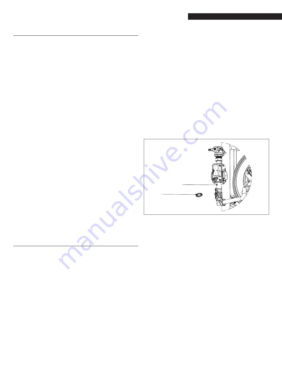
− Unscrew the swivel joint indicated in Fig. 14 to separate the
valve from the connection pipe with the fan
Swivel joint
LP Orifice
Fig. 14
Natural Gas to LP Gas Conversion
− Separating the two components, the hole where the gas
passes with its gasket can be accessed
− Place the provided metal orifice (Fig. 14) between the two
gaskets (N° on orifice: 9.5)
− Tighten the swivel joint
− Switch the main power supply to ON
− Use the 905PB inner display to enter the appliance
configuration menu and change the parameter #95 from
“17” to “18”. Follow this path: menu --> setting -->
appliace --> configuration --> password --> boiler -->
managing --> 98 appliace setting (from “17” to “18”) -->
configuration confirmed (“yes”) repeat the same sequence
for each dependent.
− Reopen the gas shut-off valve
− Adjust the O
2
parameter as explained in next chapter
− Affix the gas type label from the gas conversion kit to the
appliance.
− Repeat above process for all heat exchangers.
Additional parts (such as a high voltage ignition transformer) may
be required for reliable ignition of the propane. Please consult the
Riello factory prior to all conversions from natural gas to propane.
Содержание Array AR 3000
Страница 1: ...cod Doc 0079789 rev 5 09 2018 Array AR 3000 AR 4000 US INSTALLATION AND OPERATION MANUAL...
Страница 39: ...39 SHUTDOWN 39 APPENDIX WIRING DIAGRAM DEPENDENT 5 6 7 8 RIGHT DOOR...
Страница 69: ...69...
Страница 70: ...70...
Страница 71: ...71...


